PTT output
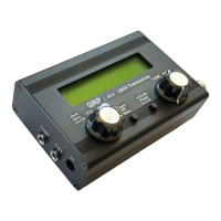
The QMX PCB has a 3.5mm stereo jack as PTT output.
The “Tip” connection is pulled to ground during transmit, when Q13 is switched on by the
microcontroller.
The “Ring” connection is pulled to +5V during transmit when Q12 is switched on by the
microcontroller.
A common standard 3.5mm stereo audio cable with 3.5mm plugs at each end may be used
without modification between the QMX and the QRP Labs 50W PA (which uses the positive-going
+5V signal on the “ring” and makes no connection to “tip”.
During transmit, the microcontroller activates ONE of the PTT signals; you may configure which
one, according to your needs.
It should be noted that:
• The QRP Labs 50W PA may not be used in high duty cycle modes such as FT8, JS8 etc at
full power. It should be de-rated to half power operation at maximum, by using a 12V or
13.8V supply. Caution is advised.
• The 50W PA kit has a built-in Low Pass Filter and is designed for signal band operation
only.
• The PTT output must be enabled per band, by connecting a terminal emulator to QMX.
Refer to the operation manual for details.
QMX assembly Rev 1.00e 60

 Loading...