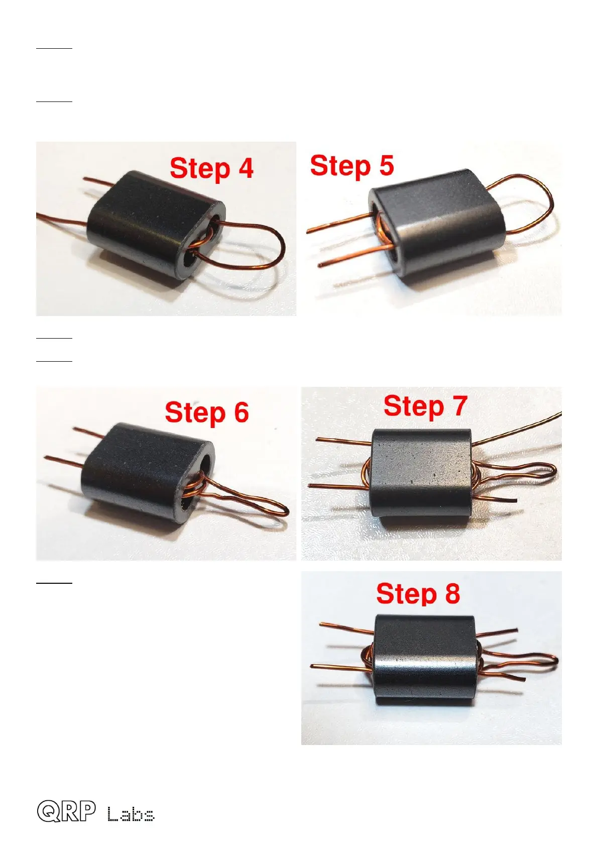
Step 4: Now pass the wire back through the bottom hole of the binocular core, from right to left;
but do not pull it tight. Leave a small loop as shown in the photograph. This will be soldered into
the center-tap pad on the PCB.
Step 5: Wind the wire through both the top hole of the binocular core and the bottom hole, pulling
it a little tight as normal; this forms the final turn of the 3-turn primary winding. You end up with the
wire coming out of the bottom left hole as shown; cut it to about 1cm protrusion.
Step 6: Squeeze together the center-tap to try to avoid subsequent confusion.
Step 7: Start the 3-turn secondary winding by pushing the wire from right to left through the bottom
hole of the binocular core, then from left to right through the top hole. This is the first turn.
Step 8: Push the wires through both holes two
more times to create the second turn: right to left
through the bottom hole, then left to right through
the top hole. Now we have three turns on the
secondary. Cut the wire leaving about 1cm spare.
Remember to wind only 2 turns secondary, if
winding the transformer as 3:2 for 12V
operation.
Please refer to page 4 for details of 9V or 12V
operation choices.
QMX assembly Rev 1.00e 28

 Loading...