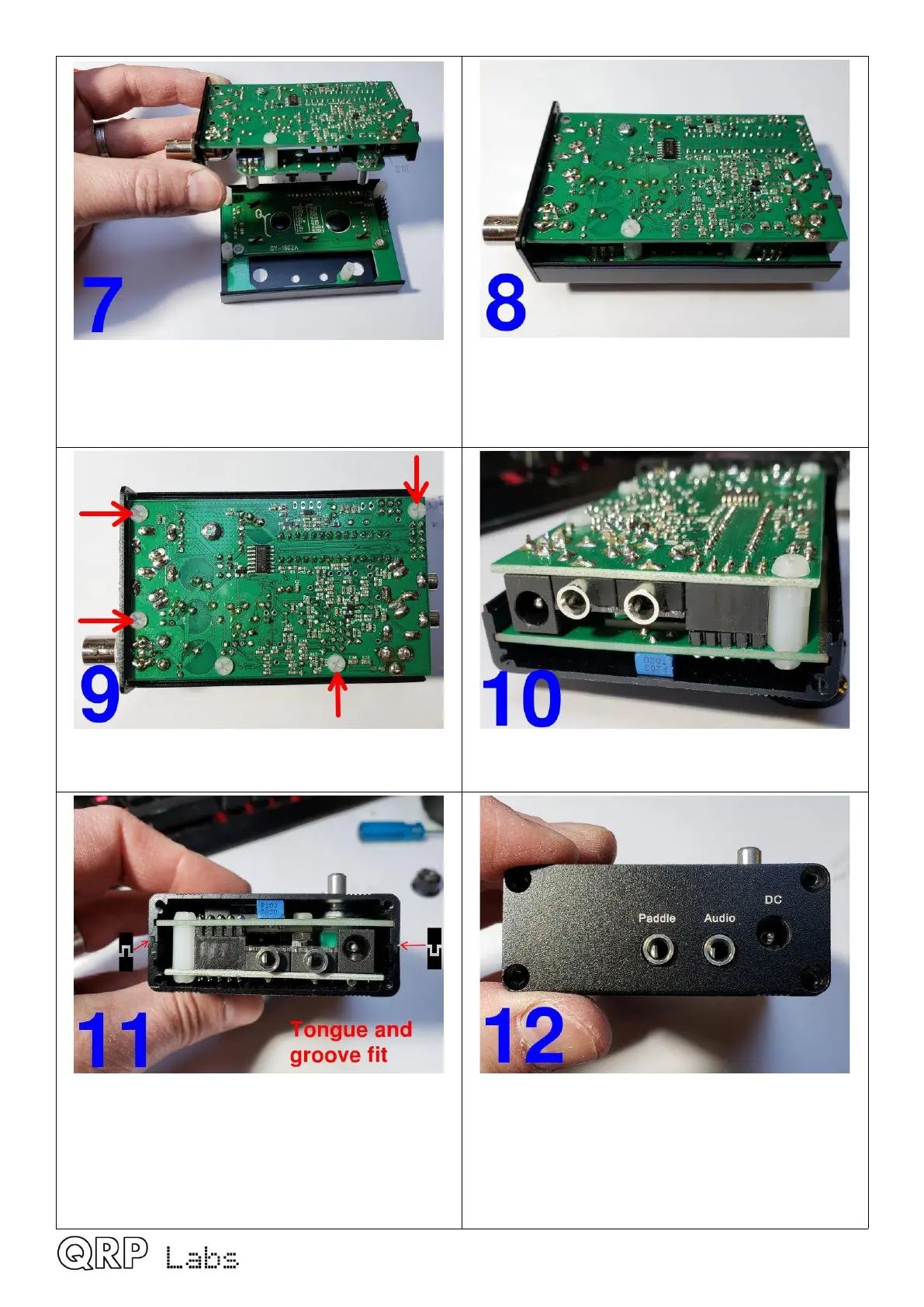
Place the front of the enclosure face down on
the bench as shown, and prepare to attach the
main board.
Align the 2x5-pin header connector between the
main and display boards; some wriggling will be
needed to get the controls to fit through the
holes in the front panel.
Fit four M3 6mm nylon screws in the positions
shown
This is how it looks from the DC connector end
Determine correct orientation of the bottom half
of the enclosure; note the tongue-and-groove
arrangement which means that the bottom half
only fits one way round! Make sure you have
the correct way.
Now bolt the left-hand side panel to the
enclosure extruded top and bottom halves using
four of the supplied small black countersunk
screws in the panel corners. The screws need
to be carefully aligned and should screw in
easily (if properly aligned).
QMX assembly Rev 1.00e 57

 Loading...