Tracks shown in BLUE are on the bottom layer. Tracks shown in RED are on the top layer. One
internal layer is used mainly for transporting digital and analog signals relatively long-distance on
the board, and these traces are shown in YELLOW. One layer is used primarily (but not
exclusively) for power rails (12V, 5V, 3.3V). These traces are shown in PURPLE. Two of the
internal layers are used ONLY for ground-plane with no exceptions. Additionally, all un-used area
on ALL the layers, is assigned as ground-plane wherever possible, with frequent ground plane
stitching vias connecting the layers on all 6 planes, at intervals not more than 0.1 inches.
For best RF low noise performance, any signal transitioning between layers should have a nearby
ground via stitching the ground-planes together, placed as close as possible, to minimize
emissions due to discontinuity of the ground return paths. Frequent ground plane stitching also
prevents the creation of internal microwave cavities which could resonate and enhance noise
propagation between harmonics of digital signals and sensitive RF signals.
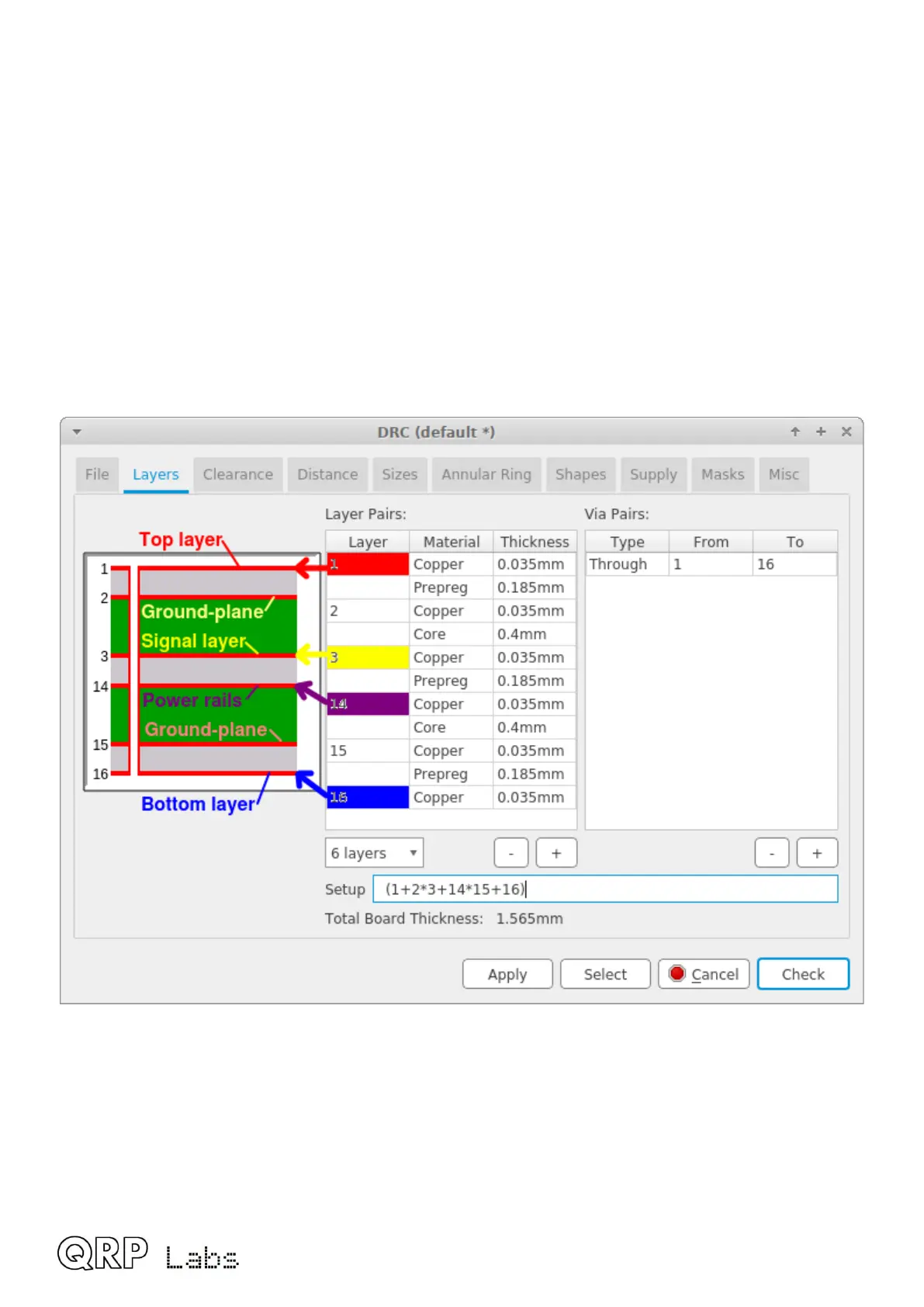
This diagram from the Eagle CAD “Design Rules Check” illustrates the layer set-up which is based
on the specification of the PCB manufacturer.
You will note that there is only one type of via, which goes through the entire board through all 6
layers. In many cases, a signal actually only needs to transition part-way through the board, for
example from the bottom layer (16) to the internal signal layer (3). Other types of via are possible,
which are called “blind” and “hidden” or “buried” vias.
Blind via: has one end on the board surface layers, and drills through to an internal layer where it
terminates. It does not have a drill hole all the way through the board, so other components and
traces could be placed on the opposite board surface or on internal layers without conflict.
QMX assembly Rev 1.00e 6

 Loading...