Chapter 10 In-service field maintenance for 2Uenclosures 95
c. Use one hand to support the weight of the CM and the other to gently withdraw the CM from its slot.
d. Place it in a static-protected location.
2. Complete the following actions to replace it with a tested good CM:
a. Examine the tested good CM to make sure it is undamaged with pins that are straight, not bent.
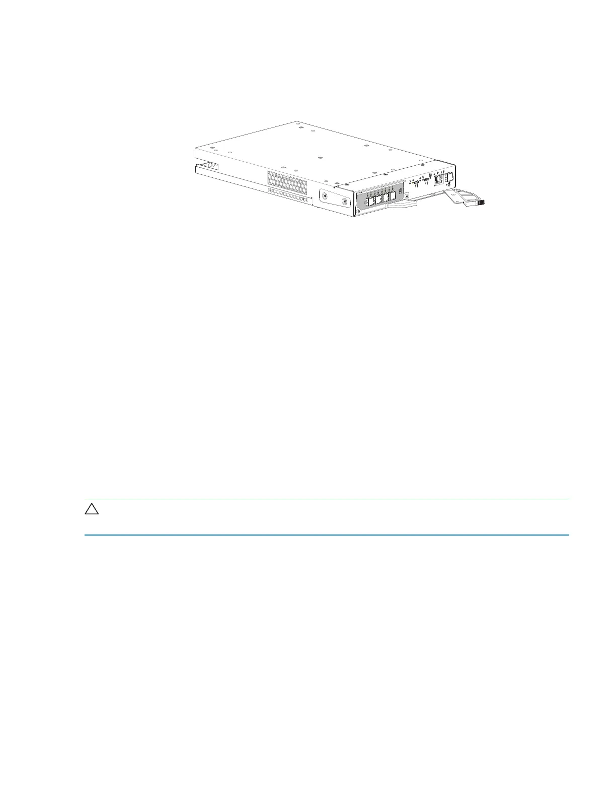
Figure 69 Replacement controller module (SAS 4-port version)
b. Facing the rear of the storage enclosure, orient the CM with the open latch identically to the one you just
removed.
c. Use one hand to support the weight of the CM and the other to guide it into the empty CM slot.
d. Exerting even pressure to the center, gently press it against the midplane until the latch closes and it
locks in place.
3. After verifying the connectors are all undamaged, reconnect all cables as they were connected before.
4. Verify that the Hardware normal LED is lit green on the replaced CM after properly inserting and seating it
in the empty slot.
5. Facing the front of the storage enclosure, verify that the Power On LED is green and there are no fault
conditions.
Replace a 2U power cooling module
Each auto-ranging power cooling module (PCM) provides power and cooling to storage enclosure modules
and components. The power supply portion of the PCM provides power to the storage enclosure within 100-
240VAC at 50-60Hz. The PCM uses standard industrial wiring with line-to-neutral or line-to-line power
connections.
CAUTION Never remove power from a power cooling module if the partner power cooling module amber
LED is lit.
The 764W DC PCM input range is -40V to -72V DC with 25 to 14A current. Each PCM has 6 LEDs to identify
various states: 4 as primary thermal and power status indicators and another 2 that used to indicate battery
status but are no longer in use. When no LEDs are on, there is no AC power to the PCM. The asterisk (*)
indicates a fault condition.
 Loading...


