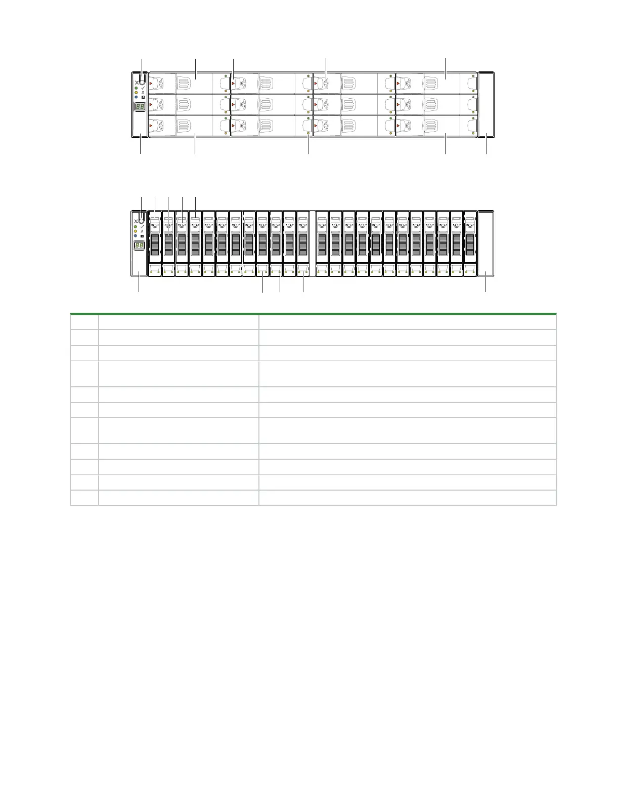
4Chapter 2 System overview
Item Description Function
1 Input button Selects and sets UID when combined with system Locate command
2 Drive 0 Responds to commands for drive logically numbered "0"
3 Release latch, drive module Allows drive module insertion onto and removal from the midplane and
slot
4 Anti-tamper lock, drive module Prevents drive module removal when locked
5 Drive 3 Responds to commands for drive logically numbered "3"
6 Operator's (ops) panel on left rack ear
flange
Connects to midplane, provides users with storage enclosure information
and status
7 Drive 8 Responds to commands for drive logically numbered "8"
8 Status LEDs, drive module Provides users with drive module status
9 Drive 11 Responds to commands for drive logically numbered "11"
10 Right rack ear cover Acts as cosmetic cover over rack flange
Figure 1 2U12 and 2U24 front panel area
 Loading...


