Chapter 7 Operation of 5U enclosures 51
In the case of a system fault condition, identified in the state column with an asterisk (*), troubleshoot the fault.
See the baseboard management controller (BMC) system event log (SEL) for detailed information.
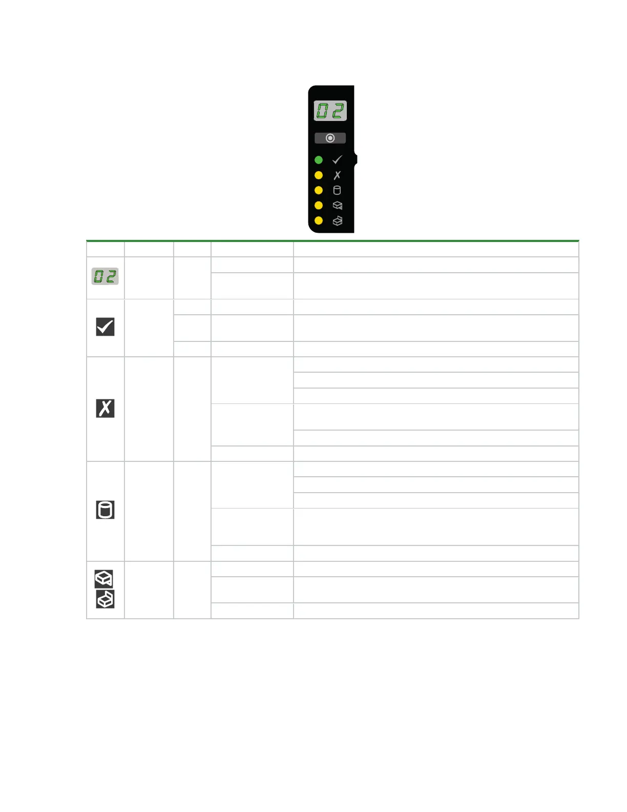
LED Type Color State Status
Unit ID Green
On Unit identification (UID) of storage enclosure (0-99)
Flashing (1s on, 1s
off)
SCSI enclosure services (SES) controlled UID or locate active
Power on
or standby
Green On Storage enclosure power is on
Amber On
Storage enclosure has AC power and is on standby as enclosure
comes online
None Off Storage enclosure AC power is off
Module
fault
Amber
On*
Ops panel completing 5s test
Module fault in rear panel area, when paired with module fault LED
Drive fault, when paired with drive fault LED
Flashing*
Unknown, invalid, or mixed module types, such as mixed drive
modules or PSUs
Vital product data (VPD) configuration error or 1²C bus fault
Off Storage enclosure rear panel area modules functioning properly
Logical
status
Amber
On*
System component hardware fault:drive, cable, or fanout card
System component hardware change of status
Drive fault caused loss of redundancy
Flashing*
System software reports an informational condition for the array,
such as a rebuild operation, with corresponding drives registering a
fault
Off System component hardware functioning properly, no errors
,
Drawer 1,
Drawer 2
hardware
fault
Amber
On* Upper, lower drawer hardware fault: drive, cable, or fanout card
Flashing (1s on, 1s
off)
UID or locate active for Drawer 1, Drawer 2 sideplane or drive
Off Upper, lower drawer hardware functioning properly
Figure 42 5U84 operator's panel LEDs
Interpret drawer LED panels
Each storage enclosure drawer bezel contains 2 LED panels to reflect drawer status and activity, 1 for each
sideplane. Each sideplane represents a data path within the drawer. You can monitor the drawer LED panels
to determine drawer status in combination with the user interface content.
 Loading...


