Chapter 6 Operation of 2U enclosures 45
Interpret controller module LEDs
There are two redundant controller modules (CMs) that use a series of LEDs to reflect host connectivity status.
You can monitor the LEDs from the rear panel area to determine system status in combination with the user
interface content. You cannot mix controller types when daisy-chaining controllers.
In the case of a fault condition, identified in the state column with an asterisk (*), troubleshoot the fault and take
appropriate corrective action.
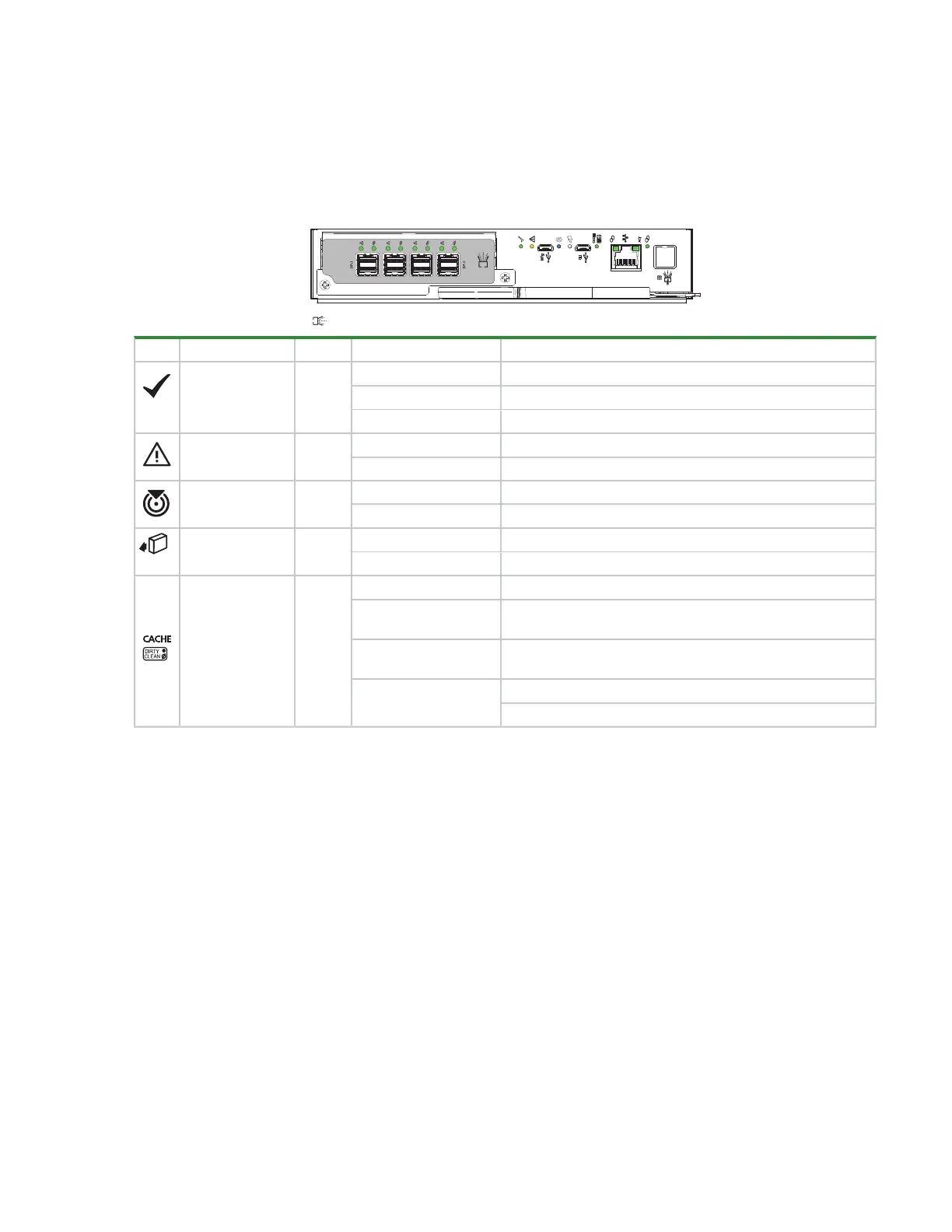
LED Type Color State Status
Hardware normal Green
On CM functioning properly
Flashing Part of sequence as CM comes online, on standby
Off CM power is off, CM is offline, or CM has a fault condition
Hardware fault Amber
On* CM hardware fault
Off CM functioning properly
Identify Blue
On Unit identification (UID) active
Off Normal state, no query for UID active
OK to remove White On Ready for removal, the cache is clear
Off Do not remove the CM, cache still contains unwritten data
Cache status Green
On Cache contains unwritten data, CM functioning properly
Fast flash (1s on, 1s
off)
Cache is active, cache flush in progress
Slow flash (3s on, 1s
off)
Cache self-refresh in progress after cache flush
Off
Cache is clear
System is coming online
Figure 37 Controller module LEDs applicable to all variations
Additional port LEDs on the CM relate to host connectivity and network activity, depending on the controller
type.
 Loading...


