8Chapter 2 System overview
1 2 3 4 5 6
7
8 9 10
11
12
13
14
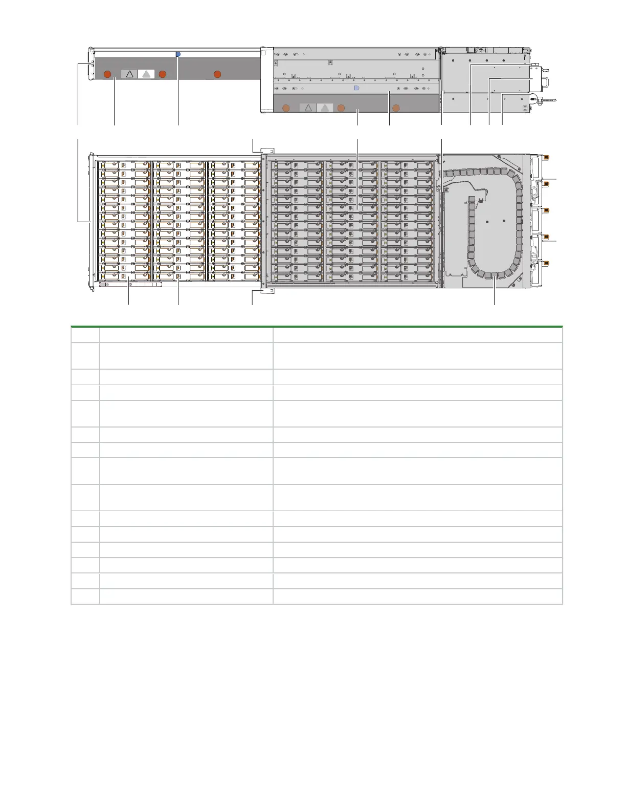
Item Description Function
1 Drawer front with keyed anti-tamper lock
and 2 drawer latches
Prevents or provides access to DDICs, contains dual drawer panel
LEDs for drive activity and fault status
2 Right sideplane Registers DDIC activity and fault conditions for the primary host path
3 Drawer latch for top drawer: Drawer 1 Locks drawer open to access slots logically numbered from 0 to 41
4 Operator's (ops) panel on left rack ear
flange
Connects to midplane, provides users with storage enclosure
information and status
5 Bottom drawer: Drawer 2 Contains slots logically numbered from 42 to 83
6 Drawer slide
Supports full extension to service position and access to DDICs
7 Midplane
Connects modules to system controls (
Authorized service personnel
only
)
8 Controller module (CM) Provides data redundancy and acts as the nerve center of the storage
enclosure
9 Fan cooling module (FCM) Provides redundant regulation of temperature and airflow
10 Power supply unit (PSU) Provides redundant regulation of power
11 Drive module in its carrier (DDIC) Provides redundant data storage
12 Locking mechanism Secures full connection of DDIC
13 Right rack ear cover Cosmetic
14 Cable management system Protects cabling associated with the related drawer
Figure 5 Profile and top views of fully populated 5U84 drawers
Controller module components
Both controller modules (CMs) manage the flow of data to and from the storage enclosure. Each CM provides
a very specialized, solutions-specific interaction that depends on your system configuration and software
implementation, including RAIDfunctions, management functions, failover and failback procedures, and
multipath procedures.
 Loading...


