Chapter 2 System overview 7
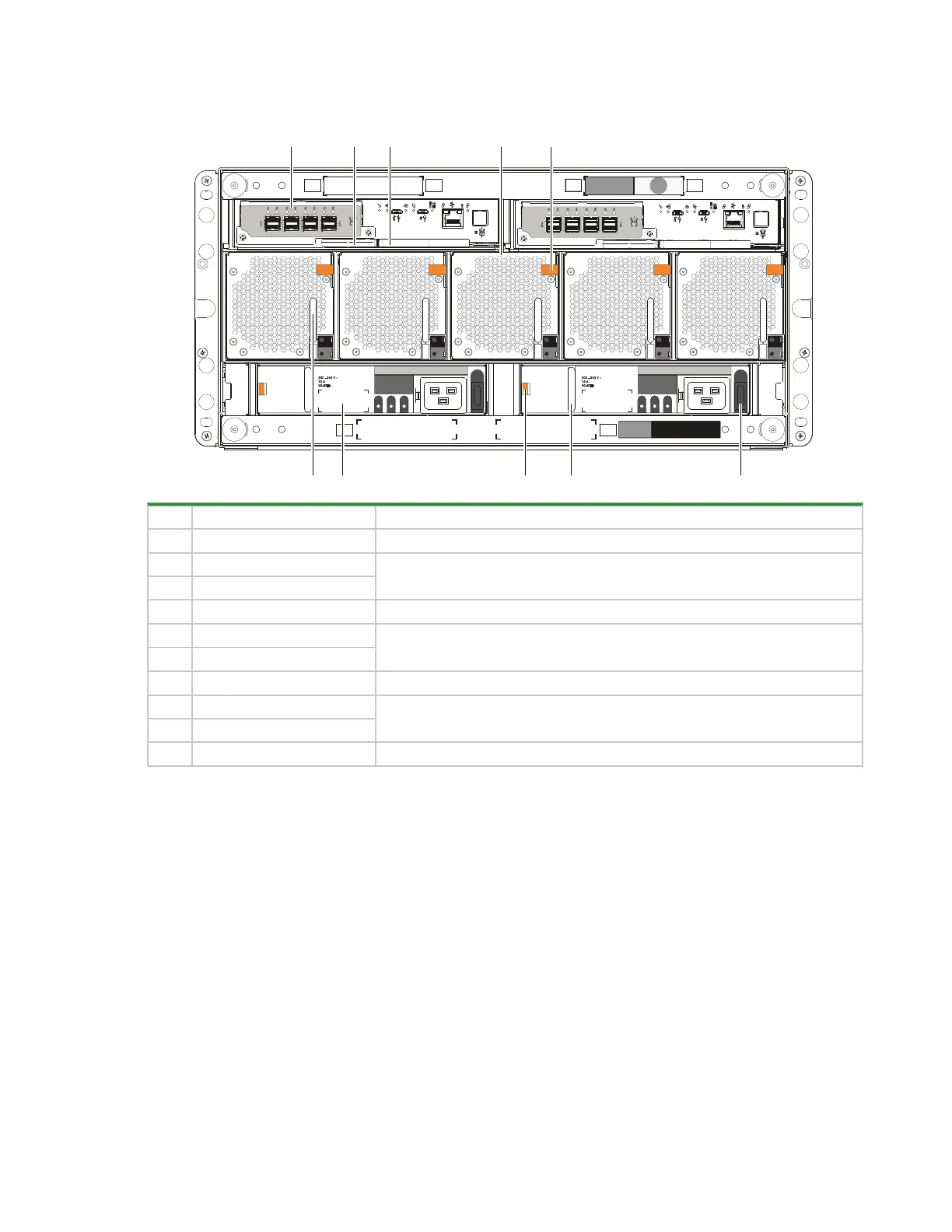
The rear panel area provides you access to modules designed for power, thermal cooling, and host
connectivity.
12Gb/s
12Gb/s
1 2 3 4 5
6 7
8 9 10
Item Description Function
1 Controller module (CM) Provides data redundancy and is the nerve center of the storage enclosure
2 CM release latch
Provides full contact with midplane or releases CM for inspection and service
3 CM release latch and handle
4 Fan cooling module (FCM) Provides redundant regulation of temperature and airflow
5 FCM release latch
Provides full contact with midplane or releases FCM for inspection and service
6 FCM pull handle
7 Power supply unit (PSU) Provides redundant regulation of power
8 PSU release latch
Provides full contact with midplane or releases PSU for inspection and service
9 PSU pull handle
10 PSU power switch Powers on or off the storage enclosure
Figure 4 5U84 rear panel area
Two sliding drawers hold DDICs and their related sideplanes.
l
Two drawers each can contain 42 DDICs. Drawer slides lock the drawer in the fully open service position,
so require release latch activation to close the drawer.
l
DDICs slide into 42 slots in each drawer. The upper drawer, Drawer 1, contains slots logically numbered
from 0 to 41 in rows moving from top to bottom, then from left to right. The lower drawer, Drawer 2, contains
slots logically numbered from 42 to 83, following the same pattern.
 Loading...


