ESP-SMT Smart Modular Control System
56
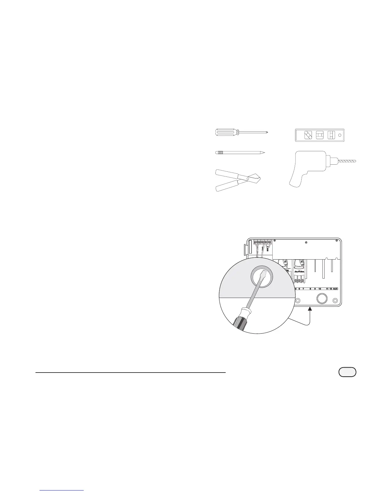
Installation Tools Required
a. Phillips slot-head screwdriver (#1, #2 & #3 tip)
b. Marking pencil for template
c. Wire stripper
d. Torpedo level
e. Drill bit & hammer drill (if installing in masonry or
concrete, select drill bit accordingly)
Optional Items:
• If the communication wire run is greater than 25 feet,
additional wire will be required (#18 AWG or #16
AWG, 2 strand UV rated wire recommended - 200 feet
maximum distance from controller to sensor)
• Ladder to reach sensor mounting location
Valve (Zone) and Communication Wire
Entrances
The ESP-SMT controller has three “knockouts” available for
routing valve & sensor communication wires, two on the
underside of the cabinet, and one on the back.
A
The underside of the cabinet has two knockouts sized for
either a 1” or 1-1/4” PVC male adapter.
B
To use the larger hole, turn the cabinet upside down. Place
the blade of a slot-head screwdriver in the groove around
the knockout. Tap the handle of the screwdriver to punch
in the knockout in two places.
C
To route field and communication wires through the back
of the cabinet, use the 1-1/4” knockout provided. Punch
out the knockout, as described in step 2.
a.
b.
c.
d.
e.
A
B
 Loading...