Reference Manual V1.19 Software Versions 4.xx
003R-682-119 Page 9
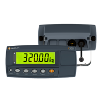
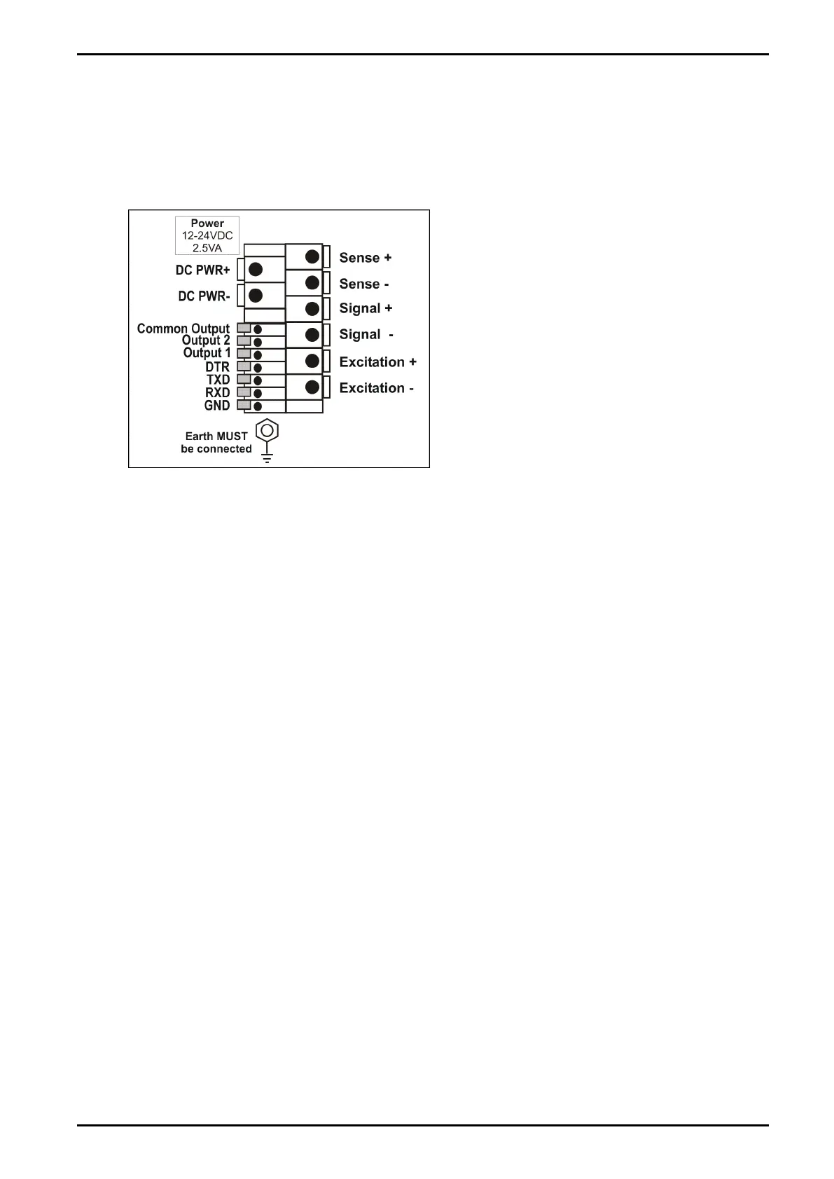
3.6. Cable Connections
All cable connections are made to the rear of the instrument using screwless terminals. Wires
must be stripped of insulation by at least 10mm. To install, depress the orange lever beside
the terminal required and push wire into the hole. Release the lever and pull gently on the
wire to ensure it is securely trapped in the terminal. It is not necessary to tin the ends of the
wire with solder or to add crimp ferrules to the wires, however, these techniques are also
compatible with the terminals and may ultimately make for a neater job.
Figure 2: Cable Connections
3.7. DC Power (DC PWR +, DC PWR –)
The DC supply need not be regulated, provided that it is free of excessive electrical noise and
sudden transients. The instrument can be operated from a high-quality plug-pack as long as
there is sufficient capacity to drive both it and the load cells.
If an optional battery pack is fitted, then the supplied charging system must be used.
3.8. Load Cell Connection
3.8.1. Load Cell Signals and Scale Build
Very low output scale bases may be used but may result in some instability in the weight
readings when used at higher resolutions. Generally speaking, the higher the load cell output,
or the lower the number of divisions, the greater the display stability and accuracy.
The instrument can display the millivolt-per-volt reading that can be used to check scale base
signal output levels. For more information, refer to TEST (Special Test Functions) page 40.
The instrument may be connected for either 4-wire or 6–wire operation. To correspond with the
actual cabling installation the instrument must be configured in setup to the correct setting. For more
information, refer to CABLE (4-Wire or 6-Wire) page 34.
 Loading...