Reference Manual V1.19 Software Versions 4.xx
003R-682-119 Page 15
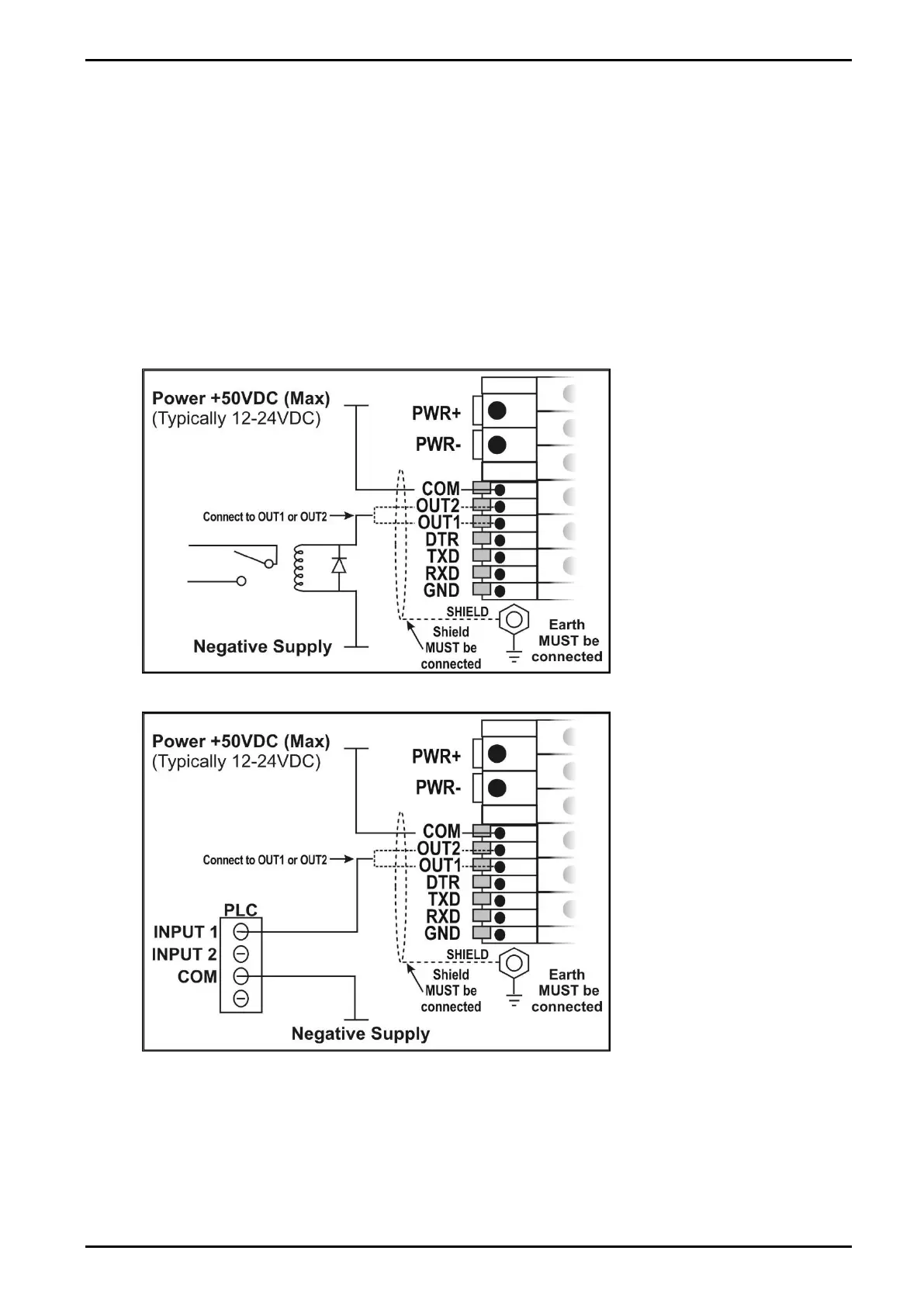
3.9.3. Outputs
The output drivers for the instrument are isolated open emitter transistor drives that are
capable of driving up to a total of 300mA. This configuration allows for the direct connection of
the instrument outputs to most types of PLC.
The voltage applied to the COM terminal appears on the output lines (i.e. OUT1 and OUT2)
when the outputs are active (e.g. to connect to a PLC connect +24V to the common terminal).
The outputs can then be connected directly to PLC inputs so when activated are active the
PLC will see a 22V signal (approx. - the exact switch loss will depend on loading of the
output).
To drive external loads (e.g. relays), connect the relay coil positive supply to the output
common and the output line directly to one side of the relay coil. Connect the other end of the
relay coil to the negative supply. It is recommended that fly-back diodes or transient
suppressors be fitted across relay coils to limit switching noise.
Figure 11: Instrument Outputs to Drive Relay
Figure 12: Instrument Outputs to Drive PLC
 Loading...