Reference Manual V1.19 Software Versions 4.xx
Page 10 003R-682-119
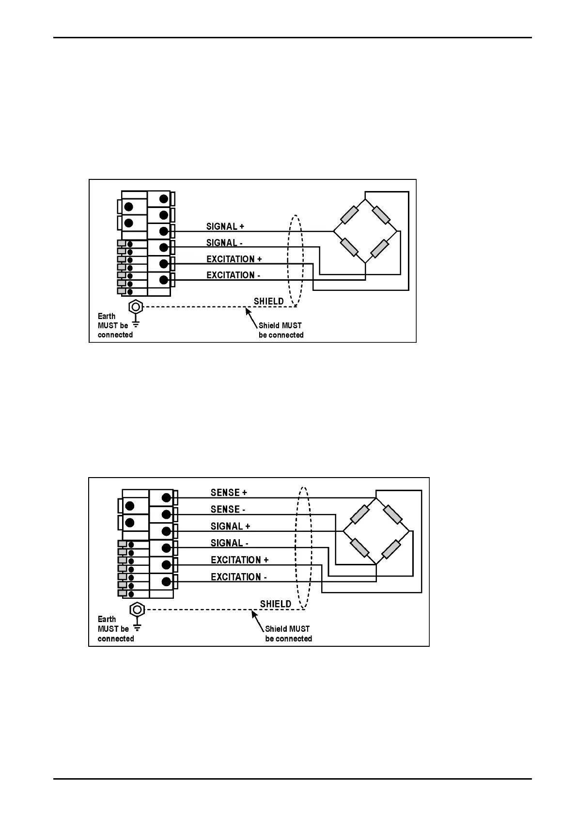
3.8.2. 4-Wire Connection
The minimum connectivity requirements are the connection of four wires (i.e. Excitation + and
– along with Signal + and –). Internally the instrument has a precision analogue switch that
connects the Sense + and – lines directly to the Excitation + and – lines when 4-wire mode is
selected.
A 4-wire connection is only suitable for short cable runs. Where long cable lengths are
needed, a 6-wire extension is required to maintain accuracy.
The BUILD:CABLE option must be set to 4 to allow for 4-wire connection. Refer to CABLE (4-Wire
or 6-Wire) page 34.
Figure 3: 4-Wire Connections
3.8.3. 6-Wire Connection
The excitation and signal lines are connected the same as for a 4-wire installation. The extra
two wires (Sense + and –) should be connected to the Excitation + and – lines as close as
possible to the load cell itself. Typically these connections are made in a load cell termination
box.
The BUILD:CABLE option must be set to 6 (the default) to allow for 6-wire connection. Refer to
CABLE (4-Wire or 6-Wire) page 34.
Figure 4: 6-Wire Connections
 Loading...