104 Rockwell Automation Publication 7000-UM202H-EN-P - November 2023
Chapter 2 Power Component Definition and Maintenance
16. Apply a 60Hz, 33% duty cycle signal to the OP1 fiber optic input.
17. Verify that the diagnostics transmitter LED, OT1, is on.
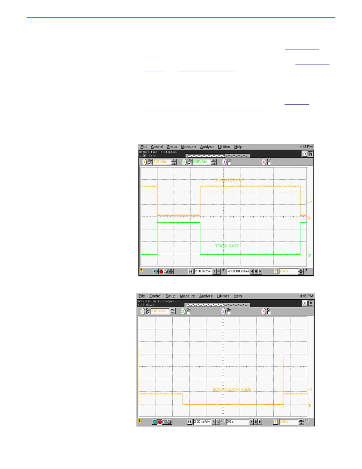
18. Verify that the signals at TP9 and TP8 are as shown in Figure 93 on
page 104.
19. Verify that the signal between TP1 and TP2 is as shown in Figure 94 on
page 105 and Figure 95 on page 105
20. Remove the jumper between TB3-1 and TB3-2.
21. Apply a constant fiber optic signal to the OP1 input.
22. Apply a 60 Hz, 33% duty cycle signal, at a 0 to +2V level, between the TB1-2
input and COM. Verify the signals as illustrated from Figure 93
to
Figure 96 on page 106. In Figure 96 on page 106, there should be a 220 μS,
+/-20 μS time between the rising edge of the U4-pin7 pulse and the falling
edge of the TP7 signal.
Figure 92 - Gating Pulses
Figure 93 - SCR Gating Pulses

 Loading...


