200 Rockwell Automation Publication 7000-UM202H-EN-P - November 2023
Appendix D Insulation Resistance Test
values start segmenting the drive system down into smaller
components and repeat the test on each segment to identify the source
of the ground fault. This implies isolating the line side of the drive
from the machine side by removing the appropriate cables on the DC
Link reactor.
You may need to completely isolate the DC Link reactor from the drive, at
which point you must disconnect all four power cables. You must ensure
that you have electrically isolated all electrical components to be tested
from ground.
Items that may produce lower than expected readings are surge
capacitors at the motor terminals, motor filter capacitors at the output of
the drive. The testing procedure must follow a systematic segmentation
of electrical components to isolate and locate a ground fault.
The motor filter capacitors and line filter capacitors (if applicable) may
result in the test results being lower than expected. These capacitors have
internal discharge resistors designed to discharge the capacitors to
ground. If you are uncertain of the test results, disconnect the output
capacitors.
5. Reconnect connections between power circuit and low voltage control.
a. Reconnect the ribbon cables “J1”, “J2”, and “J3” in all the VSBs. Do not
cross the cable connections. Mixing the feedback cables may result in
serious damage to the drive.
6. Reconnect the power circuit to the system ground.
Voltage Sensing Boards
a. Securely reconnect the two ground conductors on the VSBs.
The two ground connections on the VSB provide a reference point for
the VSB and enable the low voltage signal to be fed to the ACBs. If you
do not connect the ground conductor, the monitored low voltage
signal could then rise up to medium voltage potential, which is a
serious hazard to avoid at all times. Always ensure the ground
conductors on the VSB are securely connected before applying
medium voltage to the drive.
Failure to connect both ground connections on the voltage sensing
board will result in high potential in the low voltage cabinet within the
drive that will damage the drive control, and possible cause injury or
death to personnel.
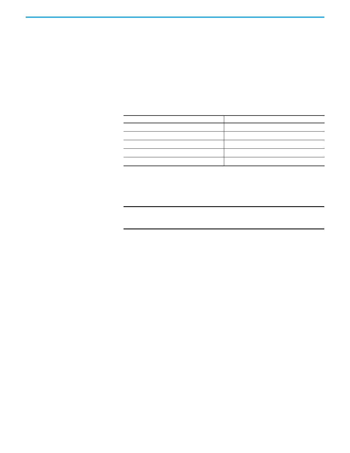
Type of Drive Minimum Insulation Resistance Value
Liquid-cooled drive
200 M
Ω
Air-cooled drive
1k M
Ω
Drive with input/output capacitors disconnected
5k M
Ω
Isolation transformer
5k M
Ω
Motor
5k M
Ω
IMPORTANT Humidity and dirty standoff insulators may also cause leakage to ground
because of tracking. You may have to clean a 'dirty' drive prior to
commencing the test.