38 Rockwell Automation Publication 7000-UM202H-EN-P - November 2023
Chapter 2 Power Component Definition and Maintenance
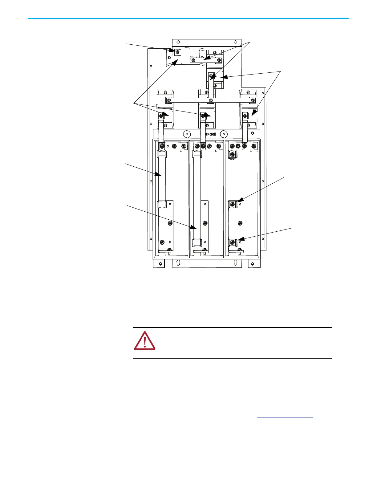
Figure 30 - Transient Suppression Network
Replacing Metal-Oxide Varistors
Metal-oxide varistors (MOV) are part of the TSN located within the connection
cabinet.
1. Ensure there is no power to the equipment.
2. Observe the locations of the connecting links.
3. Detach the connecting links by removing the screws.
4. Using a screwdriver remove the screws at the base.
5. Replace the MOV (polarity is not an issue).
6. Continue by replacing the screws and connecting links.
Each MOV panel is grounded. One MOV (see Figure 30 on page 38
for location)
must connect to the grounding lead.
Ground location
Varistors
5 kV fuse example
7.2 kV fuse example
Connecting links
Varistors
5 kV fuse location
7.2 kV fuse location
ATTENTION: To prevent electrical shock, disconnect the main power
before working on the drive. Verify that all circuits are voltage-free
using a hot stick or appropriate voltage-measuring device. Failure to
do so may result in injury or death.

 Loading...


