2
2-5
1
2
1
2
U2
U1
L
N
U1
U2
1
2
L
N
1
2
U2
U1
L
N
12
N
1L2L3L
WHT
BLK
1
2
12
1
2
U2
U1
L
N
N
U1
U2
1
2
L
L
N
1
2
U2
U1
L
N
WHT BLK
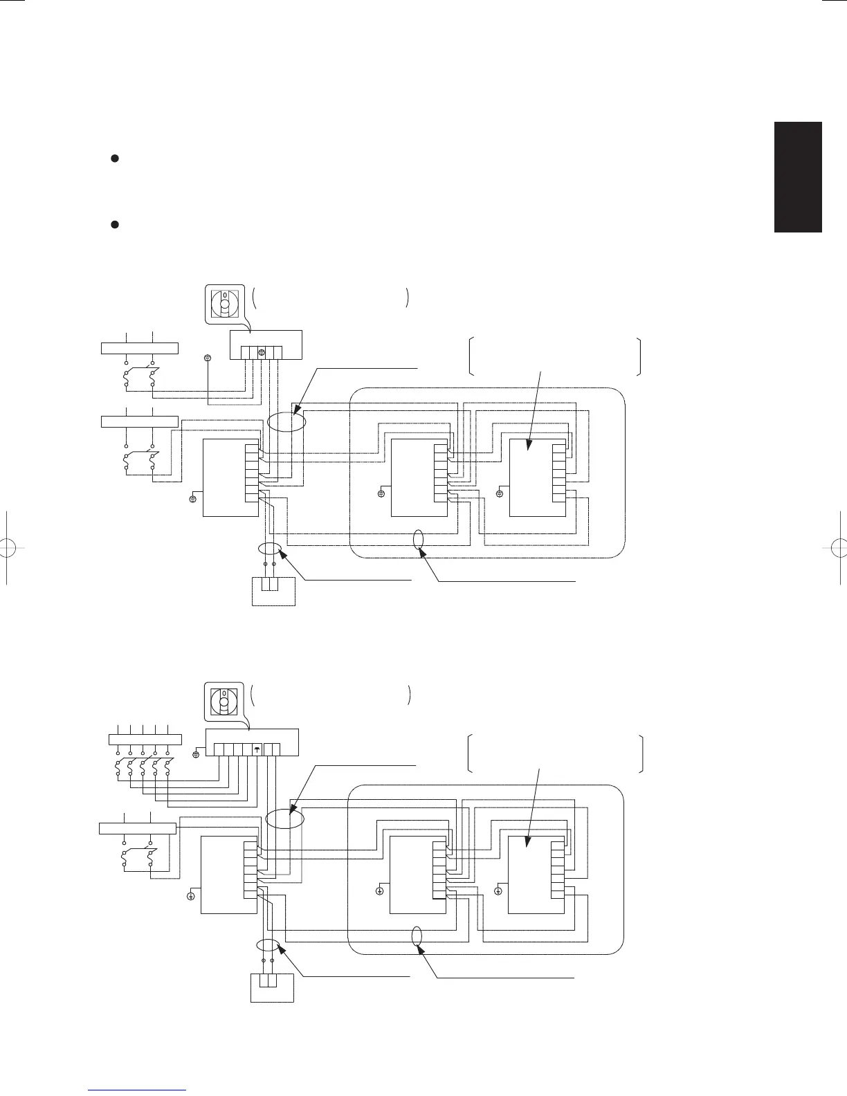
2-8. System Control
System control refers to the link wiring connection for control of simultaneous operation multi systems, group
control, and main-sub remote controller control.
2-8-1.Basic wiring diagram 1
Single type and simultaneous operation multi system
Simultaneous operation multi system
Up to 4 (Double-Twin) indoor units can be connected to 1 outdoor unit for operation.
(However, coordinate the outdoor unit capacity and the total capacity of the indoor units.)
(It is not possible to connect individual remote controllers for independent operation.)
Be careful to avoid miswiring when connecting the wires.
(Miswiring will damage the units.)
(for single-phase outdoor unit)
Fig. 2-5-1
System address rotary switch
(Set to “0” at the time of shipment.)
For a simultaneous operation multi
system, a maximum of 4 indoor units
can be connected to 1 outdoor unit.
Leakage breaker
Leakage breaker
Ground
Ground
Ground
Ground
Outdoor unit
Indoor
unit
Indoor
unit
Indoor
unit
Inter-unit control wiring
(Optional)
Wired remote
controller
Remote controller wiring
Remote controller communication
wiring for group control
Fig. 2-5-2
(for 3-phase outdoor unit)
System address rotary switch
(Set to “0” at the time of shipment.)
For a simultaneous operation multi
system, a maximum of 4 indoor units
can be connected to 1 outdoor unit.
Leakage breaker
Leakage breaker
Ground
Ground
Ground
Ground
Outdoor unit
Indoor
unit
Indoor
unit
Indoor
unit
Inter-unit control wiring
(Optional)
Wired remote
controller
Remote controller wiring
Remote controller communication
wiring for group control
SM830160-03ClassicPAC-iA4.ind55SM830160-03ClassicPAC-iA4.ind55 2010/02/1610:28:082010/02/1610:28:08
 Loading...