7
<Procedure>
Be sure to turn the main power OFF before performing the steps below.
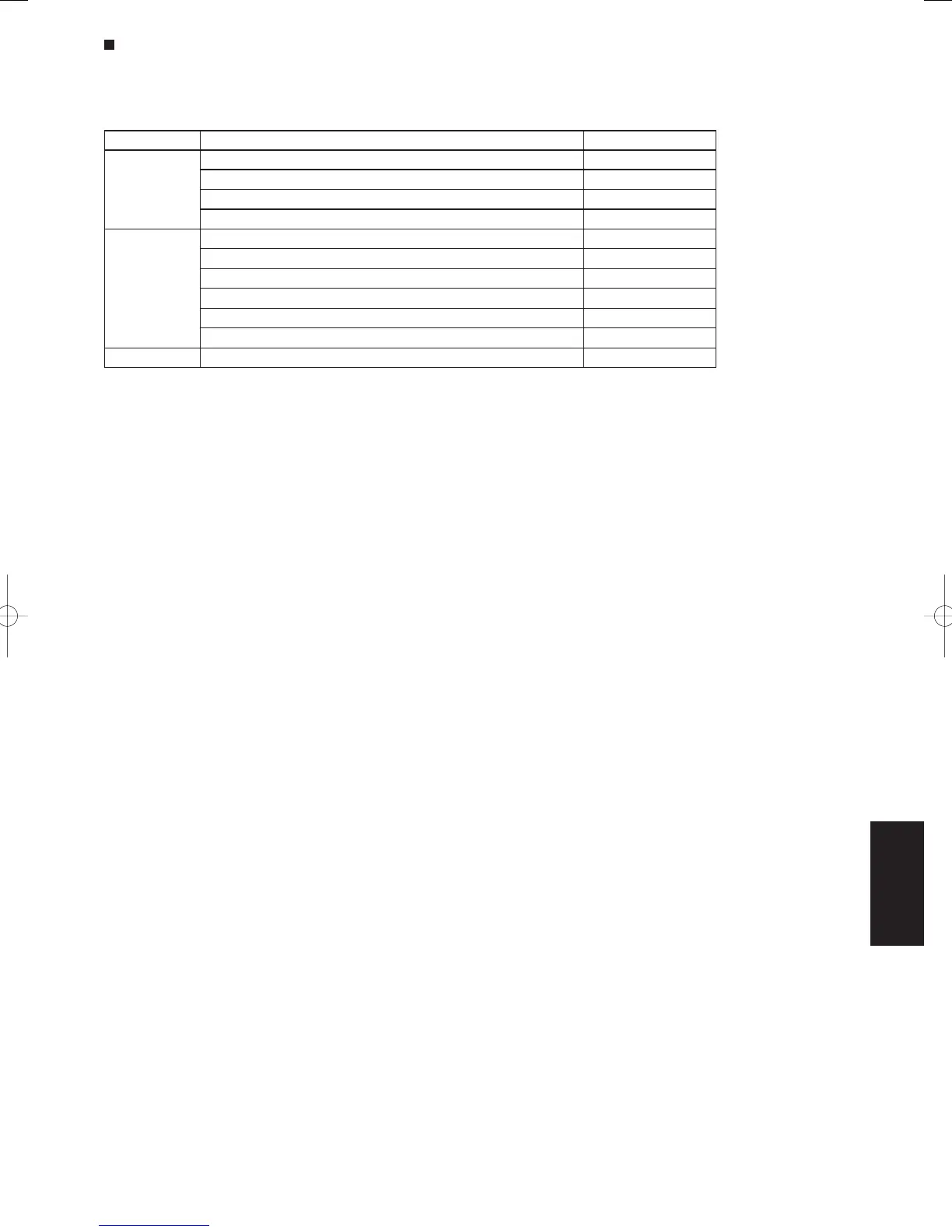
(1) Check the optional product that will be used from the table below.
Setting No. Optional part name Optional part No.
[1]
Super long-life filter AFT-LS140A
Oil guard panel PNR-S140AAG
Ammonia deodorizing filter AFT-DS140AG-AM
Optical regeneration deodorizing filter AFT-DS140AG-PC
[3]
High-performance filter, colorimetric 65% type AFT-MS140A
High-performance filter, colorimetric 90% type AFT-HS140A
Air cleaning unit AFT-ES140A
Deodorant filter AFT-DS140AG
Air-blocking material (for 3-direction discharge) INS-DS140A
Air-blocking material (when a discharge duct is connected) INS-DS140A
[6] Air-blocking material (for 2-direction discharge) INS-DS140A
Setting No.
[1]
: Go to (2).
Setting No.
[3]
: Go to (3).
Setting No.
[6]
: Go to (4).
DC Fan Tap Change Procedure
(2) Setting No. [1]
Open the cover of the electrical component box, and connect the supplied short-circuit connector (2P, yellow) to
short-circuit pin TP1 (2P, red) on the indoor unit control PCB.
(3) Setting No. [3]
Open the cover of the electrical component box, and connect the supplied short-circuit connector (2P, yellow) to
short-circuit pin TP3 (2P, yellow) on the indoor unit control PCB.
(4) Setting No. [6]
Open the cover of the electrical component box, and connect the supplied short-circuit connector (2P, yellow) to
short-circuit pin TP6 (2P, white) on the indoor unit control PCB.
7-15
SM830160-03ClassicPAC-iA4.ind1515SM830160-03ClassicPAC-iA4.ind1515 2010/02/1610:30:522010/02/1610:30:52

 Loading...


