8
8-19. RCS-SS80BG.WL
1. Accessories
No. Accessories Quantity
1 Operation panel
1
2
Display
1
3 Remote control
1
4
Remote control holder
1
No. Accessories Quantity
5 AAA alkaline batteries
2
6
Users Manual
1
7 Truss self-tapping screws
4 X 16
2
8 Pan head self-tapping screws
4 X 10
2
9 Plastic clamp L150
4
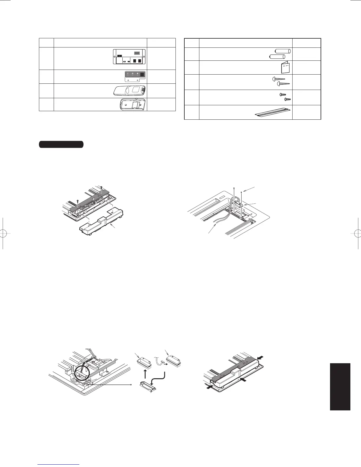
2. Accessories
Installing the Display/Operation Panel
Installing the Operation Panel
1. Remove the 2 screws and remove cover A from the back of the panel. (Fig. 8-15)
2. Fasten the operation panel to the location in the diagram below with the 2 enclosed screws (4 X10). (Fig. 8-16)
3. Pass the wiring for the display (W2, 6P white connector) through the back of the panel.
Installing the Display
1. Cover B is tted inside cover A, so remove the 1 screw and detach it by pressing on it from the front side of the
panel. (Fig. 8-17)
2. Connect the wiring (W2) for the display that is sticking out from the operation panel and t the display into the
panel. Make sure the 6P white connector is rmly connected all the way in.
3. Bend the lead wire of the display into shape so it does not come in contact with the louver shaft. There is a
groove in the circled part in diagram 3 that is for passing wire through; press the lead wire into this groove so
there is no slack in it.
4. Attach cover A. When doing so, press it securely into the place indicated by the arrow in Fig 8-18.
5. Shape the lead wire of the operation panel appropriately and fasten it with the enclosed plastic clamp.
6. Install the ceiling panel.
Resin Panel
Fig. 8-15 Fig. 8-16
Fig.
8-17 Fig.
8-18
Cover A
Display wiring (W2)
Enclosed screws
(4 X10)
Operation Panel
Cover B
Display
Connect
8-17
SM830160-03ClassicPAC-iA4.ind1717SM830160-03ClassicPAC-iA4.ind1717 2010/02/1610:31:202010/02/1610:31:20
 Loading...