2
2-30
3-1
3-2
1-1
1-2
2-1
2-2
2-3
3-3
3-4
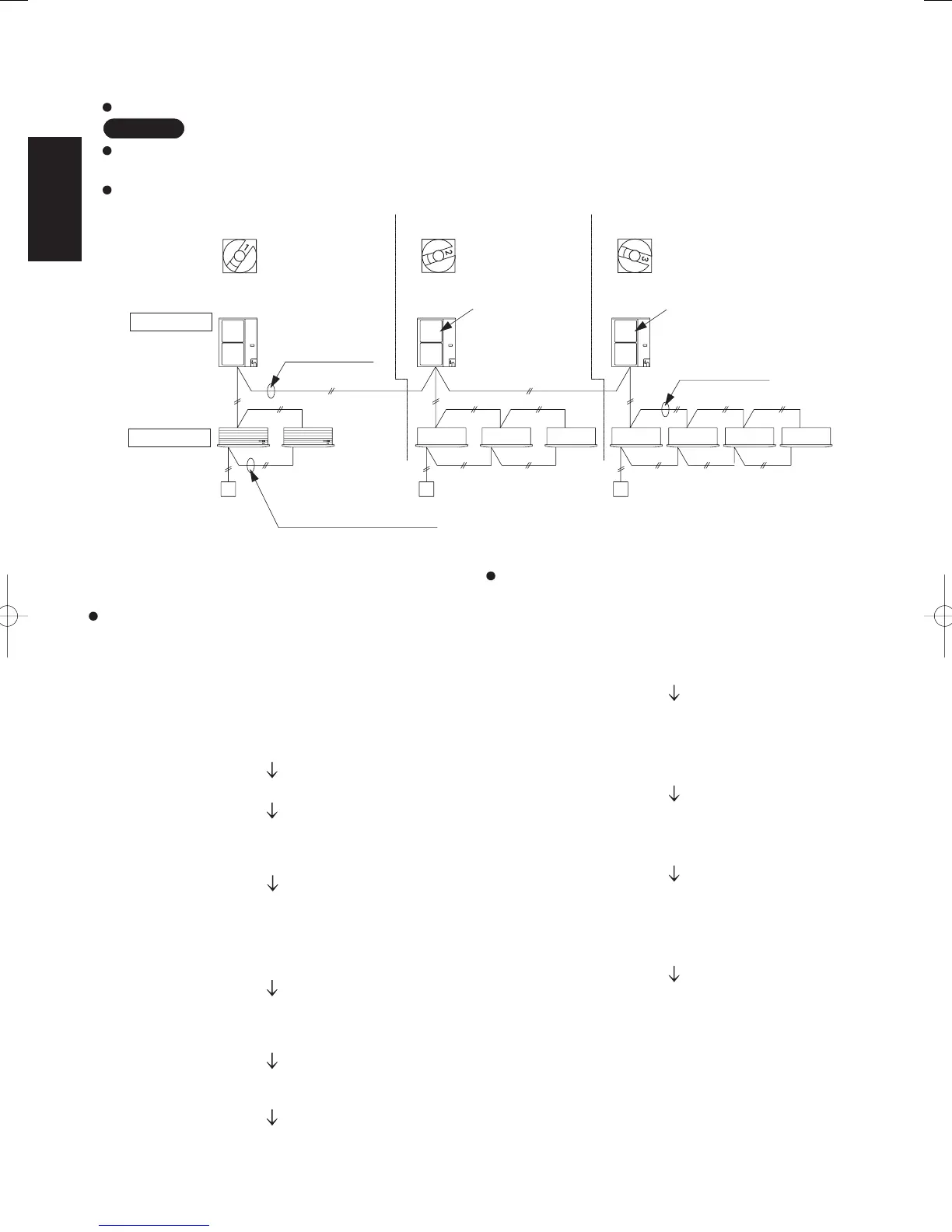
2-32. Automatic Address Setting
2-32-1. Basic wiring diagram
Link wiring
NOTE
A terminal plug (black) is attached to each of the outdoor unit control PCBs. At only one outdoor unit, leave the terminal
plug short-circuit socket on the “Yes” side. At all the other outdoor units, change the socket (from “Yes” to “No”).
A maximum of 8 indoor units can be connected to 1 remote controller for group control.
Fig. 2-28
System address
rotary switch on the
outdoor unit PCB
Refrigerant system No. 1
(Change setting to “1”)
Inter-unit control
wiring
Terminal plate 1, 2
No. 1
Terminal plate 1, 2
Outdoor unit
Indoor unit
Remote controller
Remote controller communication
wiring for group control
No. 2
No. 3
(Change setting to “2”) (Change setting to “3”)
Refrigerant system No. 2 Refrigerant system No. 3
Remote controller Remote controller
Inter-unit control
wiring
Change the terminal
plug (black) short-
circuit socket
(2P DIP switch (black)
is attached due to
a type of model.)
Change the terminal plug (black)
short-circuit socket
(2P DIP switch (black) is
attached due to a type of model.)
Automatic address setting from the outdoor unit
(XM type)
Case 1
If the power can be turned ON separately for the
indoor and outdoor units in each system, the indoor
unit addresses can be set without running the
compressor.
(1) Turn on the indoor and outdoor unit power for
refrigerant system 1.
Press and hold the automatic address setting button
(black) for 1 second or longer at the outdoor unit
where the power was turned ON.
Communication for automatic address setting begins.
LED 1 and 2 on the outdoor unit control PCB blink
alternately, and turn OFF when address setting is
completed.
<Approximately 4 – 5
minutes are required.>
(2) Next, turn ON the power only at the indoor and
outdoor units in a different system. Press the
automatic address setting button (black) on the
outdoor unit.
LED 1 and 2 on the outdoor unit control PCB blink
alternately, and turn OFF when address setting is
completed.
Repeat the same procedure for each system and
complete automatic address setting.
(3) Operation using the remote controller is now
possible.
Case 2
If the power cannot be turned ON separately for the
indoor and outdoor units in each system:
The compressors must be run in order to automatically
set the indoor unit addresses. Therefore perform this
step after completing the refrigerant tubing work.
(1) Turn ON the power to the indoor and outdoor units in
all refrigerant systems.
When setting addresses in cooling mode
(2) Short-circuit the mode-change pin at the outdoor unit
where automatic address setting will be performed.
Then press the automatic address setting button
(black).
When setting addresses in heating mode
(2) Press the automatic address setting button (black) at
the outdoor unit where automatic address setting will
be performed.
(3) LED 1 and 2 blink alternately. The compressors begin
running in Cooling (or Heating) mode.
Communication for automatic address setting begins,
using the temperature changes at the indoor units.
<All indoor units are in operating status.>
Address setting is completed when the compressors
stop and the LED indicators turn OFF.
<Approximately 15 minutes is required for 1 system.>
If address setting fails, LED 1 and 2 blink
simultaneously and the alarm contents are displayed
at the remote controller.
(4) After 1 system is completed, be sure to press the
automatic address setting button (black) at the other
outdoor units to complete automatic address setting in
the same way for each system.
(5) Operation using the remote controller is now possible.
SM830160-03ClassicPAC-iA4.ind3030SM830160-03ClassicPAC-iA4.ind3030 2010/02/1610:28:152010/02/1610:28:15
 Loading...