5-8
5
5-4. Details of Alarm Messages
SPW-C256/366VH
Alarm Details
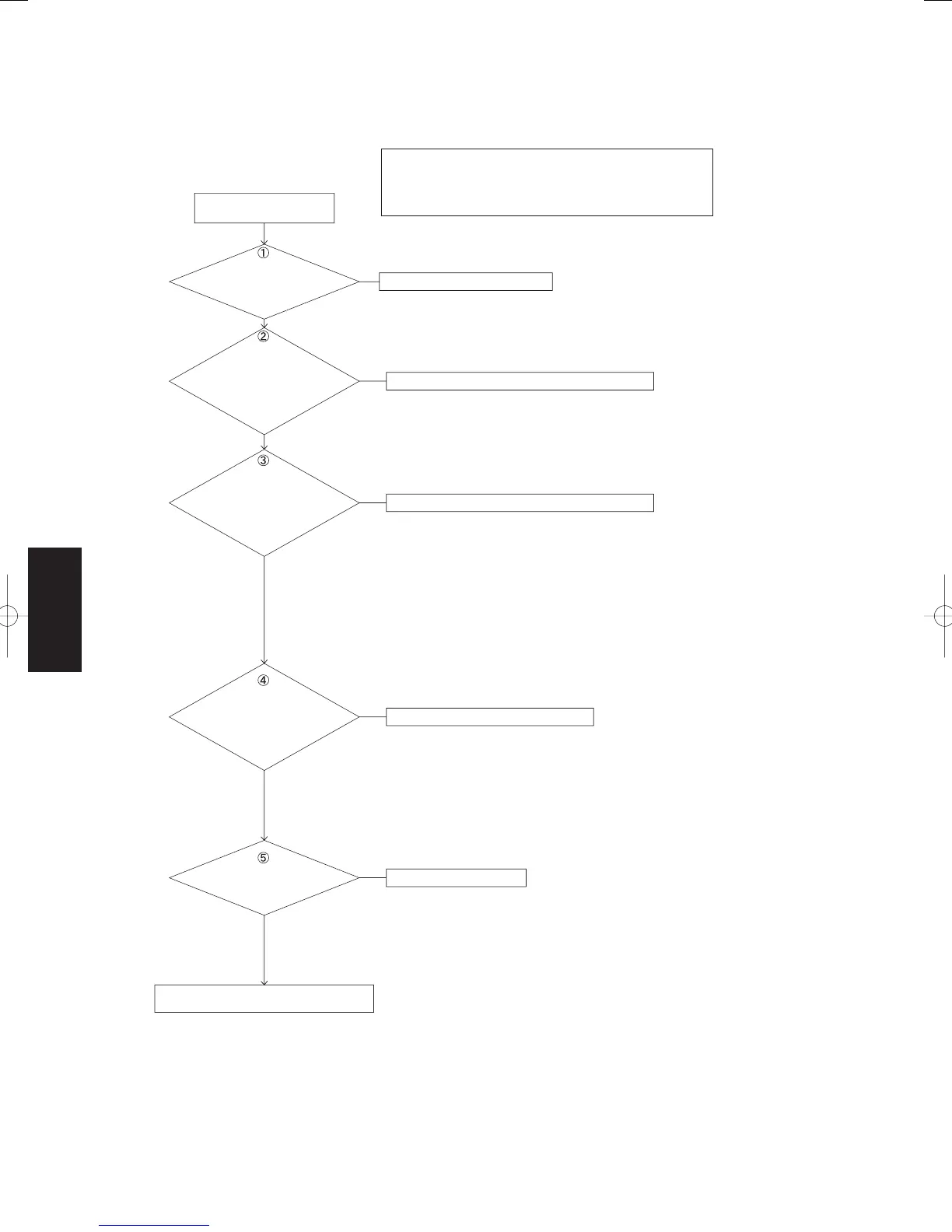
(1-1) [Alarm “P29”]
No
Start of defect diagnosis
Is the power voltage correct?
No
Improve the power voltage line.
Check the following:
Check to ascertain that the power voltage is within the permissible range of 198 to 264V
for indoor and outdoor units regardless of whether the compressor is operating or not.
* Pay special attention to whether the voltage drops after compressor operations while
measuring.
Repair the wiring connectors.
Compressor's wiring connector
3P : white
No (The CT detected value is abnormal.)
Replace the outdoor unit control PCB.
When the CT detected value is abnormal, the alarm occurs and the compressor stops
after 1-minute operation.
Verify the CT current values by performing the following steps.
Con rm that the difference between CT current detected values (*) and the current value
(measured by clamp meter) of power source wiring (between outdoor unit
power terminal and control PCB; red, white, blue) is within aproximately 1A.
* Veri cation method of CT current detect
1. With the outdoor unit maintenance remote controller
Check with the code "14" with the temperature sensor display function.
2. With the indoor unit remote controller
Check with the sensor address "14" of the temperature sensor display function.
No (Abnormal resistance value)
Replace the outdoor unit control PCB.
• Veri cation method
Measure the resistance at all areas on the HIC control mounted on the outdoor unit
control PCB.
Refer to the page 5 - 12.
Replace the outdoor unit control PCB if the readings are below permissible values.
No (Defective insulation)
Replace the compressor.
• Potential cause:
Insulation failure caused by the compressor lock.
• Veri cation Method
Remove the wires from the connectors on the top of the compressor. Measure
the insulation resistance of the U, V and W phases and con rm that they are 1MΩ or
more.
Yes
Yes
Yes
Yes
Yes
Are the
compressor wiring
connector and U/V/W connections
on the compressor
terminal
OK?
Is the
detected values of CT
current (current values) during
compressor operation
normal?
Are the resistance
values permissible at all
areas in HIC mounted on
outdoor unit control
PCB?
Is the insulation on the
compression OK?
Replace the outdoor unit control PCB.
(No problem
with the CT
detected value)
(No problem with
the resistance value)
(No problem with
the insulation)
Start-up failure of the compressor (will not start up)
Related parts
• Outdoor unit control PCB (Model 256 : CR-C256VH)
(Model 366 : CR-C366VH)
SM830160-03ClassicPAC-iA4.ind88SM830160-03ClassicPAC-iA4.ind88 2010/02/1610:30:052010/02/1610:30:05
 Loading...