Chapter 8 Operating Instructions
DME4000
104 © SICK AG • Germany • Subject to change without notice 8014584/ZN33/2017-07
Troubleshooting and
Explanation of Terms
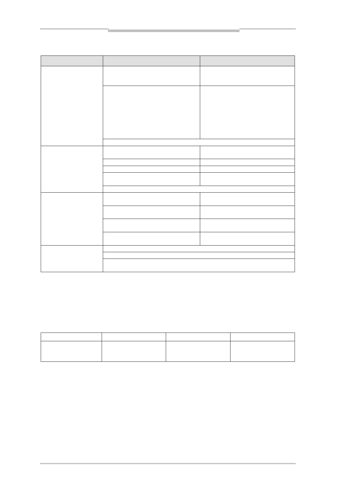
Problem Cause Remedy
(PROFIBUS diagnosis)
Check supply voltage, voltage off/on,
if not self-repairing; Contact the
Sensor temperature not within speci-
fications
(internal temperature < –15 °C: Wait
until warm-up phase finishes. It
might be necessary to use the
sensor with heating
Sensor too warm
(internal temperature > 80 °C:
Effect: Measured value output is set to zero
(PROFIBUS diagnosis)
Light path interference due to fog,
dust or other factor
Take measures to provide uninter-
rupted light path.
Check maximum movement speed
Light path to reflector interrupted.
Can light spot always be seen on the
reflector during movement?
Effect: Measured value output is set to “0”; PLB indicator lights in display.
(PROFIBUS diagnosis)
Laser diode at end of operating life
Have replacement sensor ready for
next maintenance cycle
Light path interference due to fog or
dust
Clean optical surfaces at next
maintenance cycle
Internal sensor temperature at fringe
range
Check ambient temperature
(PROFIBUS diagnosis)
Is deactivated with Octet 9, Bit 7
Effect: The offset value set per GSD is not transmitted to sensor
Application: When the preset function is used, the offset value set during the
preset remains valid
8.2 Explanation of Terms
8.2.1 PROFIBUS
Types of sensor which do not support “Speed”:
SIV2_069d.gsd
Function „Speed“ not
activatable
All sensors are connected in a bus structure (line). Up to 32 subscribers (master or slaves) can be
connected in one segment.
The bus is connected by active bus terminators at the beginning and end of each segment. Both bus
terminators must be supplied with voltage to ensure interference-free operation.
The bus termination is not implemented in the DME. Supply voltage for the bus terminators is available
at the bus output plug. This 5 V supply voltage is indirect-coupled from the supply voltage of the DME.
The 5 V supply voltage can be loaded with 100 mA and be used for optic coupling modules if required.
Terminator: See Accessories.
If there are more than 32 subscribers, repeaters (power boosters) must be used to connect the individ-
ual bus segments.
 Loading...


