Operating Instructions Chapter 4
DME4000
8014584/ZN33/2017-07 © SICK AG • Germany • Subject to change without notice 83
Align the light spot in the middle of the reflector if necessary.
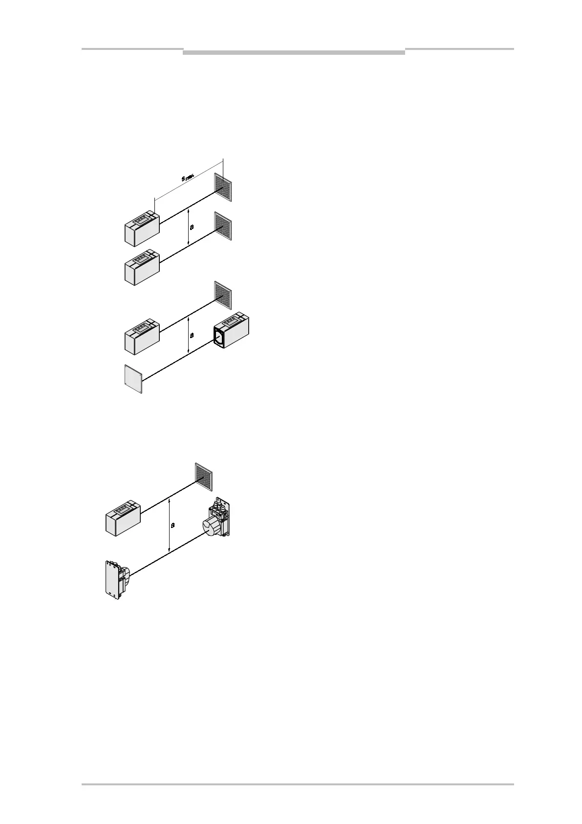
4.1.2 Arrangement of the Positions of Neighboring Distance Measuring Sensors
The distance of neighboring distance measuring sensors must be at least a
min = 100 mm to prevent
mutual interference. Depending on the range s, this distance a must equal a
min + 0.01 x smax.
Illustration 4.3 – Arrangement of Neighboring DME4000s
4.1.3 Arrangement of Distance Measuring Sensors with Neighboring Data Transmission
Illustration 4.4 – Arrangement of Neighboring DME4000 and ISD
A minimum beam distance of 100 mm should be maintained for the data transmission photoelectric
switches of the ISD300 / ISD400-1xxx / ISD400-6xxx series, independent of the maximum range s
max.
 Loading...


