Chapter 2 Operating Instructions
DME4000
72 © SICK AG • Germany • Subject to change without notice 8014584/ZN33/2017-07
2.3 Control Panel
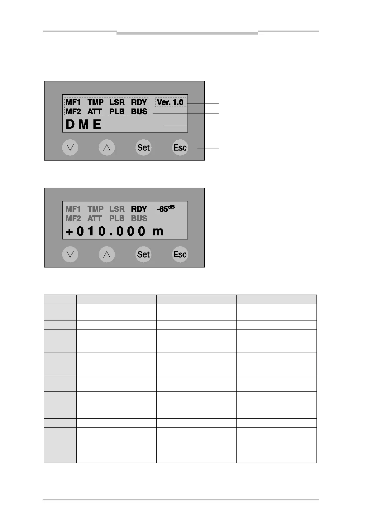
The following display of the DME4000 appears after you connect operating voltage (or after a reset):
Illustration 2.2 – Display after Connection of Operating Voltage
The DME4000 is ready to operate after approx. 1 s and displays the current measurement value:
2.3.1 Status indicators
input/output
Input/output level active
Input/output level not active
Internal sensor temperature
Internal sensor temperature at
fringe range
Internal sensor temperature OK
Reception signal level at fringe
range
measurement laser
cause: Light beam interruption,
speed > 10 m/s
At ready-to-operate state
Initialization, hardware defect
DeviceNet/CANopen interface
SSI: clock signal received
PB/DN: telegram traffic
RS 422: continuous mode
CANopen: (pre-)operational mode
PB/DN: no telegram traffic
RS 422: request mode
CANopen: stopped mode
Correction measures when there are error messages/pre-failure messages; see Troubleshooting in the
Appendix.
 Loading...


