CPU 31x-2 as DP Master/DP Slave and Direct Communication
2-20
PLC S7-300, CPU Specifications CPU 312 IFM to CPU 318-2 DP
A5E00111190-01
S7 Diagnosis
An S7 diagnosis can be requested for all the modules in the SIMATIC S7/M7 range
of modules in the user program. The structure of the S7 diagnostic data is the
same for both central and distributed modules.
The diagnostic data of a module is in data records 0 and 1 of the system data area
of the module. Data record 0 contains 4 bytes of diagnostic data describing the
current state of a module. Data record 1 also contains module-specific diagnostic
data.
You can find out how to configure the diagnostic data in the System and Standard
Functions Reference Manual.
2.6.3 Reading Out the Diagnostic Data
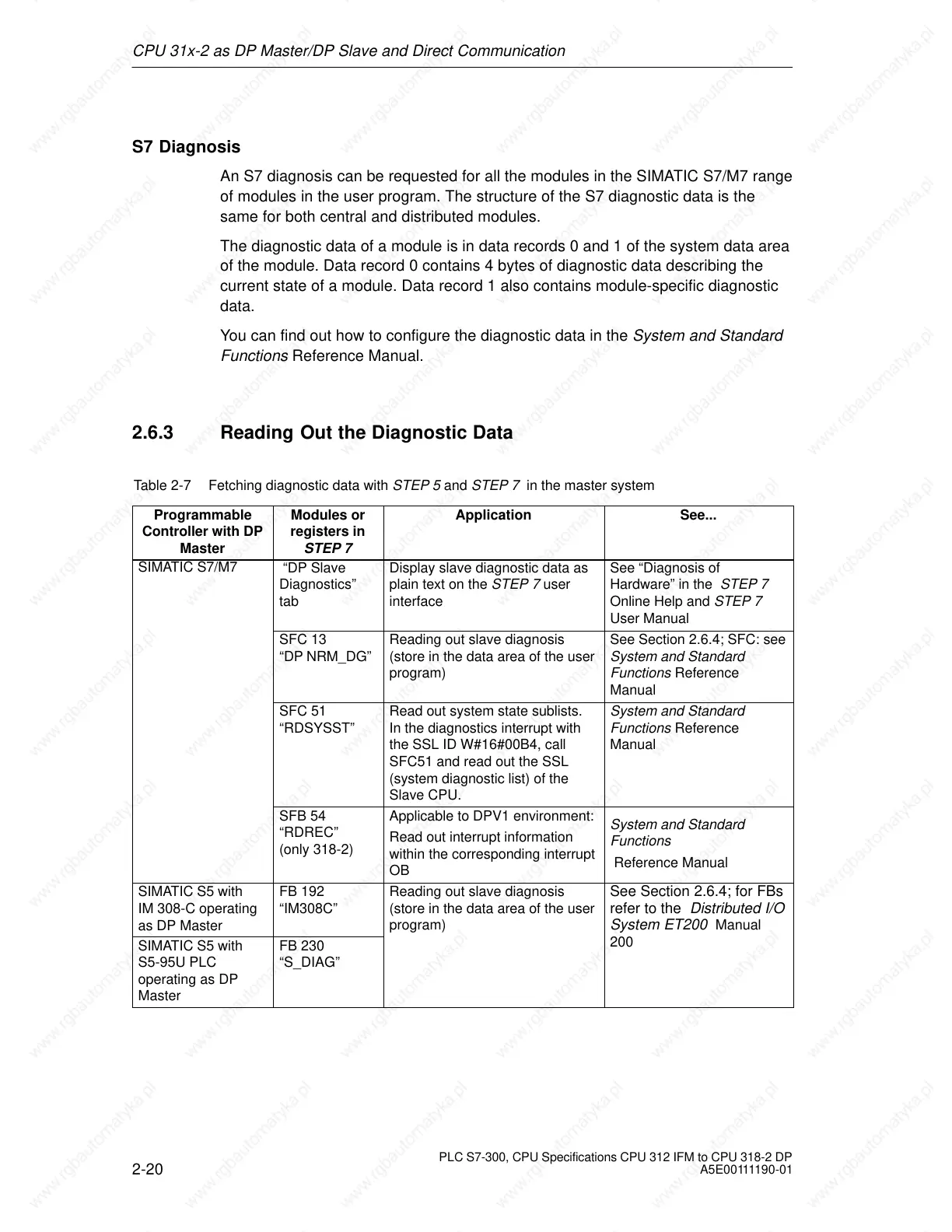
Table 2-7 Fetching diagnostic data with STEP 5 and STEP 7 in the master system
Programmable
Controller with DP
Master
Modules or
registers in
STEP 7
Application See...
SIMATIC S7/M7
“DP Slave
Diagnostics”
tab
Display slave diagnostic data as
plain text on the STEP 7 user
interface
See “Diagnosis of
Hardware” in the STEP 7
Online Help and STEP 7
User Manual
SFC 13
“DP NRM_DG”
Reading out slave diagnosis
(store in the data area of the user
program)
See Section 2.6.4; SFC: see
System and Standard
Functions Reference
Manual
SFC 51
“RDSYSST”
Read out system state sublists.
In the diagnostics interrupt with
the SSL ID W#16#00B4, call
SFC51 and read out the SSL
(system diagnostic list) of the
Slave CPU.
System and Standard
Functions Reference
Manual
SFB 54
“RDREC”
(only 318-2)
Applicable to DPV1 environment:
Read out interrupt information
within the corresponding interrupt
OB
System and Standard
Functions
Reference Manual
SIMATIC S5 with
IM 308-C operating
as DP Master
FB 192
“IM308C”
Reading out slave diagnosis
(store in the data area of the user
program)
See Section 2.6.4; for FBs
refer to the Distributed I/O
System ET200
Manual
SIMATIC S5 with
S5-95U PLC
operating as DP
Master
FB 230
“S_DIAG”
200
 Loading...

