CPUs
1-26
PLC S7-300, CPU Specifications CPU 312 IFM to CPU 318-2 DP
A5E00111190-01
Start information for OB40
Table 1-10 shows the temporary (TEMP) variables of OB40 relevant for the
“Interrupt inputs” of the CPU 312 IFM. Refer to theSystem and Standard functions
reference manual for details on the process interrupt OB.
Table 1-10 Start Information for OB 40 for the Interrupt Inputs of the Integrated I/Os
Byte
Variable Data Type Description
6/7 OB40_MDL_ADDR WORD B#16#7C Address of the interrupt triggering
module (in this case, the CPU)
8 on OB40_POINT_ADDR DWORD See Figure 1-5 Signaling of the interrupt triggering
integrated inputs
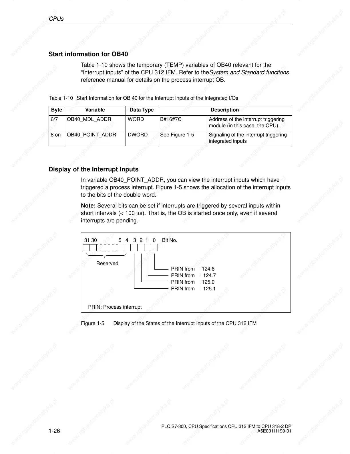
Display of the Interrupt Inputs
In variable OB40_POINT_ADDR, you can view the interrupt inputs which have
triggered a process interrupt. Figure 1-5 shows the allocation of the interrupt inputs
to the bits of the double word.
Note: Several bits can be set if interrupts are triggered by several inputs within
short intervals (< 100 s). That is, the OB is started once only, even if several
interrupts are pending.
0 Bit No.
PRIN from I124.6
54 13
2
31 30
PRIN from I 124.7
PRIN from I125.0
PRIN from I 125.1
Reserved
PRIN: Process interrupt
Figure 1-5 Display of the States of the Interrupt Inputs of the CPU 312 IFM
 Loading...

