CPUs
1-56
PLC S7-300, CPU Specifications CPU 312 IFM to CPU 318-2 DP
A5E00111190-01
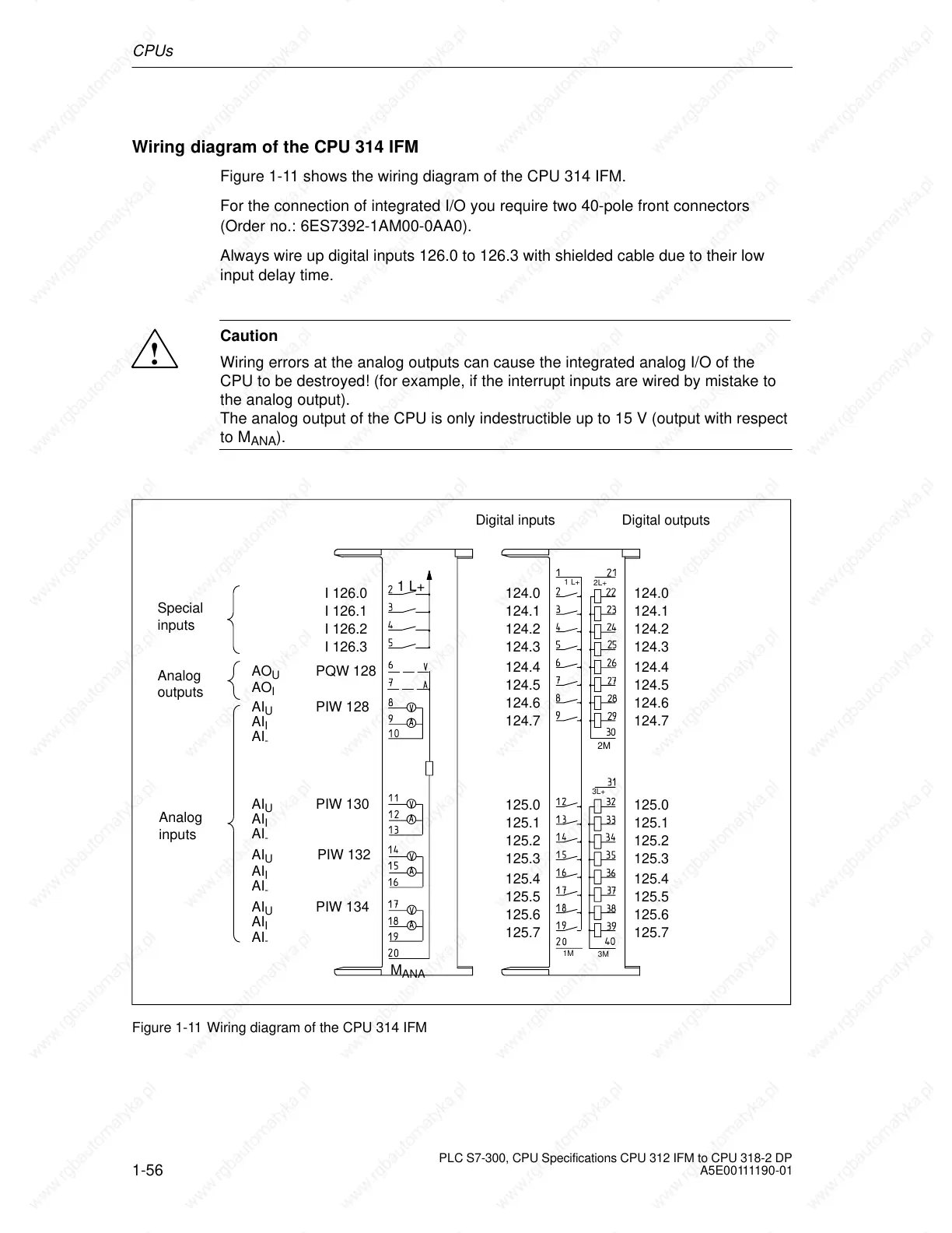
Wiring diagram of the CPU 314 IFM
Figure 1-11 shows the wiring diagram of the CPU 314 IFM.
For the connection of integrated I/O you require two 40-pole front connectors
(Order no.: 6ES7392-1AM00-0AA0).
Always wire up digital inputs 126.0 to 126.3 with shielded cable due to their low
input delay time.
!
Caution
Wiring errors at the analog outputs can cause the integrated analog I/O of the
CPU to be destroyed! (for example, if the interrupt inputs are wired by mistake to
the analog output).
The analog output of the CPU is only indestructible up to 15 V (output with respect
to M
ANA
).
1M
1 L+
3L+
3M
2L+
2M
1 L+
M
ANA
Special
inputs
Analog
outputs
Analog
inputs
I 126.0
I 126.1
I 126.2
I 126.3
PQW 128
PIW 128
PIW 130
PIW 132
PIW 134
AO
U
AO
I
AI
U
AI
I
AI
-
AI
U
AI
I
AI
-
AI
U
AI
I
AI
-
AI
U
AI
I
AI
-
124.0
124.1
124.2
124.3
124.4
124.5
124.6
124.7
125.0
125.1
125.2
125.3
125.4
125.5
125.6
125.7
124.0
124.1
124.2
124.3
124.4
124.5
124.6
124.7
125.0
125.1
125.2
125.3
125.4
125.5
125.6
125.7
Digital inputs Digital outputs
Figure 1-11 Wiring diagram of the CPU 314 IFM
 Loading...

