Cycle and Reaction times
3-9
PLC S7-300, CPU Specifications CPU 312 IFM to CPU 318-2 DP
A5E00111190-01
Bus Runtimes in the PROFIBUS Subnet
If you have used STEP 7 to configure your PROFIBUS subnet, STEP 7 calculates
the expected normal bus cycle time. On the PG you can then view the bus cycle
time of your configuration (refer to the STEP 7 User Manual).
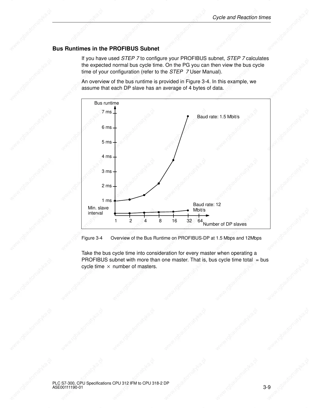
An overview of the bus runtime is provided in Figure 3-4. In this example, we
assume that each DP slave has an average of 4 bytes of data.
Bus runtime
Number of DP slaves
6 ms
4 ms
2 ms
124816 32
Baud rate: 12
Mbit/s
Baud rate: 1.5 Mbit/s
1 ms
3 ms
5 ms
7 ms
Min. slave
interval
64
Figure 3-4 Overview of the Bus Runtime on PROFIBUS-DP at 1.5 Mbps and 12Mbps
Take the bus cycle time into consideration for every master when operating a
PROFIBUS subnet with more than one master. That is, bus cycle time total = bus
cycle time number of masters.
 Loading...

