CPU 31x-2 as DP Master/DP Slave and Direct Communication
2-28
PLC S7-300, CPU Specifications CPU 312 IFM to CPU 318-2 DP
A5E00111190-01
2.6.8 Module Diagnostics
Definition
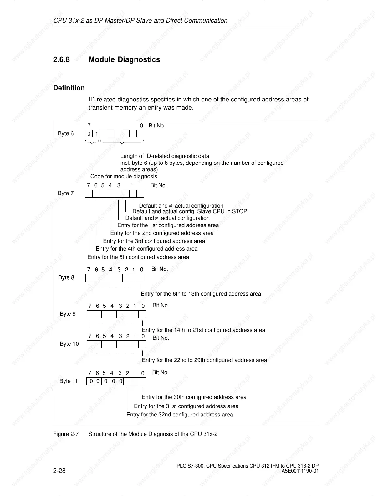
ID related diagnostics specifies in which one of the configured address areas of
transient memory an entry was made.
Byte 6
70
Bit No.
Length of ID-related diagnostic data
incl. byte 6 (up to 6 bytes, depending on the number of configured
address areas)
Byte 7
Default and actual config. Slave CPU in STOP
Entry for the 2nd configured address area
Entry for the 3rd configured address area
Entry for the 4th configured address area
Entry for the 5th configured address area
Byte 8
Entry for the 6th to 13th configured address area
Code for module diagnosis
01
7654 1
021
3
Entry for the 1st configured address area
Bit No.
Bit No.
76543
Byte 11
Entry for the 30th configured address area
Entry for the 31st configured address area
021
Bit No.
76543
Byte 8
021
Bit No.
76543
Byte 8
021
Bit No.
76543
Byte 9
Entry for the 14th to 21st configured address area
021
Bit No.
76543
Byte 10
Entry for the 22nd to 29th configured address area
021
Bit No.
76543
Entry for the 32nd configured address area
00000
Default and actual configuration
Default and actual configuration
Figure 2-7 Structure of the Module Diagnosis of the CPU 31x-2
 Loading...

