CPUs
1-43
PLC S7-300, CPU Specifications CPU 312 IFM to CPU 318-2 DP
A5E00111190-01
1.4.4 CPU 314IFM
Special Features
Integrated I/Os (wired with 40-pole front connector)
Details on analog value processing and how to connect measuring transducers,
load and actuators to analog I/O is found in the Module Data reference manual.
Figures 1-14 and 1-15 on page 1-59 show wiring examples.
Memory card
The CPU 314 IFM is available in 2 versions: with and without Memory Card slot.
With slot for memory card: 6ES7 314-5AE10-0AB0
Without slot for memory card: 6ES7 314-5AE0x-0AB0
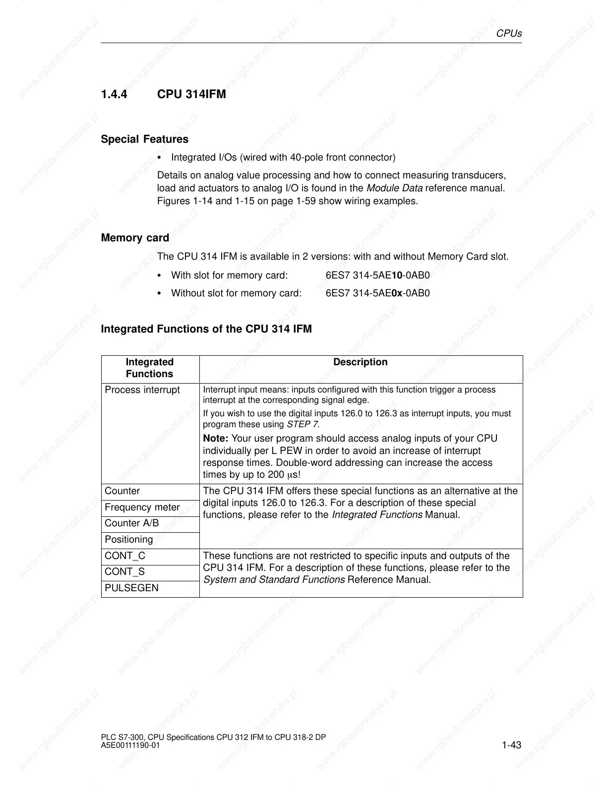
Integrated Functions of the CPU 314 IFM
Integrated
Functions
Description
Process interrupt
Interrupt input means: inputs configured with this function trigger a process
interrupt at the corresponding signal edge.
If you wish to use the digital inputs 126.0 to 126.3 as interrupt inputs, you must
program these using STEP 7.
Note: Your user program should access analog inputs of your CPU
individually per L PEW in order to avoid an increase of interrupt
response times. Double-word addressing can increase the access
times by up to 200 s!
Counter The CPU 314 IFM offers these special functions as an alternative at the
Frequency meter
digital inputs 126.0 to 126.3. For a description of these special
Counter A/B
functions, please refer to the Integrated Functions Manual.
Positioning
CONT_C These functions are not restricted to specific inputs and outputs of the
CONT_S
CPU 314 IFM. For a description of these functions, please refer to the
PULSEGEN
System and Standard Functions Reference Manual.
 Loading...

