CPU 31x-2 as DP Master/DP Slave and Direct Communication
2-25
PLC S7-300, CPU Specifications CPU 312 IFM to CPU 318-2 DP
A5E00111190-01
2.6.5 Station Status 1 to 3
Definition
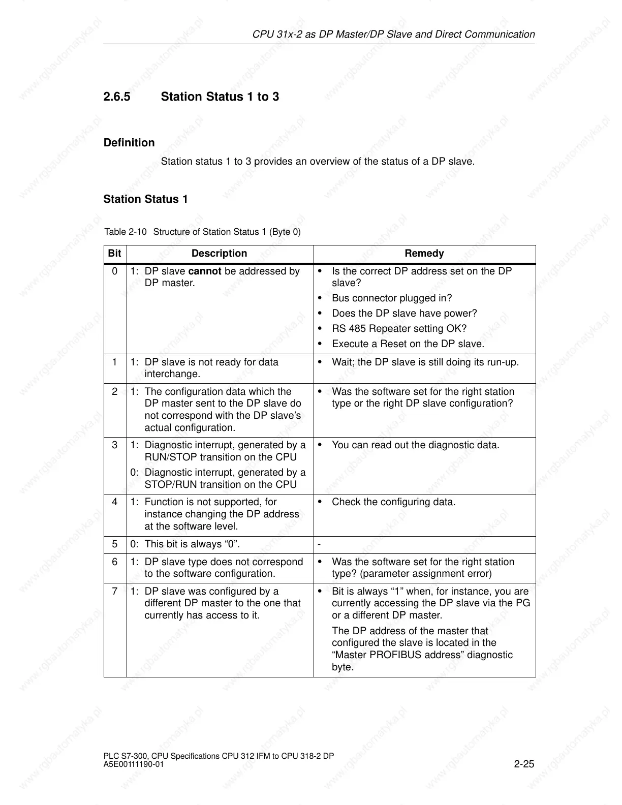
Station status 1 to 3 provides an overview of the status of a DP slave.
Station Status 1
Table 2-10 Structure of Station Status 1 (Byte 0)
Bit Description Remedy
0 1: DP slave cannot be addressed by
DP master.
Is the correct DP address set on the DP
slave?
Bus connector plugged in?
Does the DP slave have power?
RS 485 Repeater setting OK?
Execute a Reset on the DP slave.
1 1: DP slave is not ready for data
interchange.
Wait; the DP slave is still doing its run-up.
2 1: The configuration data which the
DP master sent to the DP slave do
not correspond with the DP slave’s
actual configuration.
Was the software set for the right station
type or the right DP slave configuration?
3 1: Diagnostic interrupt, generated by a
RUN/STOP transition on the CPU
0: Diagnostic interrupt, generated by a
STOP/RUN transition on the CPU
You can read out the diagnostic data.
4 1: Function is not supported, for
instance changing the DP address
at the software level.
Check the configuring data.
5 0: This bit is always “0”. -
6 1: DP slave type does not correspond
to the software configuration.
Was the software set for the right station
type? (parameter assignment error)
7 1: DP slave was configured by a
different DP master to the one that
currently has access to it.
Bit is always “1” when, for instance, you are
currently accessing the DP slave via the PG
or a different DP master.
The DP address of the master that
configured the slave is located in the
“Master PROFIBUS address” diagnostic
byte.
 Loading...

