Cycle and Reaction times
3-4
PLC S7-300, CPU Specifications CPU 312 IFM to CPU 318-2 DP
A5E00111190-01
Shortest Response Time
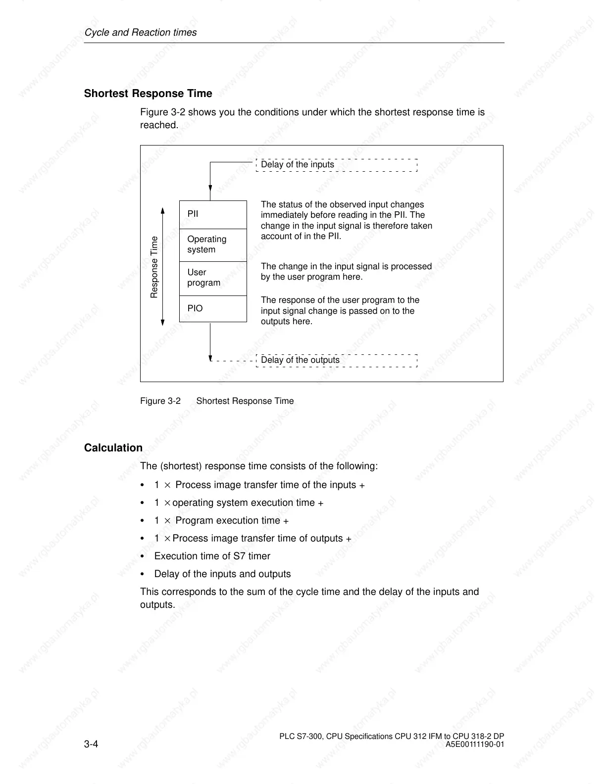
Figure 3-2 shows you the conditions under which the shortest response time is
reached.
Operating
system
User
program
PII
The status of the observed input changes
immediately before reading in the PII. The
change in the input signal is therefore taken
account of in the PII.
PIO
The change in the input signal is processed
by the user program here.
The response of the user program to the
input signal change is passed on to the
outputs here.
Response Time
Delay of the inputs
Delay of the outputs
Figure 3-2 Shortest Response Time
Calculation
The (shortest) response time consists of the following:
1 Process image transfer time of the inputs +
1 operating system execution time +
1 Program execution time +
1 Process image transfer time of outputs +
Execution time of S7 timer
Delay of the inputs and outputs
This corresponds to the sum of the cycle time and the delay of the inputs and
outputs.
 Loading...

