CPUs
1-34
PLC S7-300, CPU Specifications CPU 312 IFM to CPU 318-2 DP
A5E00111190-01
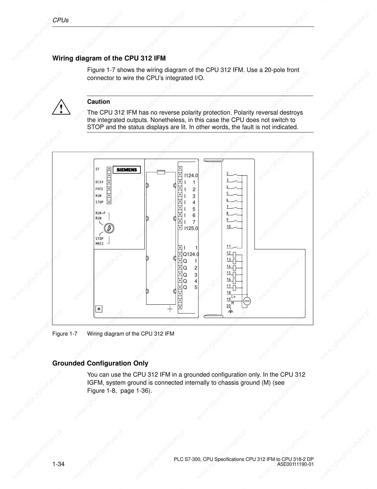
Wiring diagram of the CPU 312 IFM
Figure 1-7 shows the wiring diagram of the CPU 312 IFM. Use a 20-pole front
connector to wire the CPU’s integrated I/O.
!
Caution
The CPU 312 IFM has no reverse polarity protection. Polarity reversal destroys
the integrated outputs. Nonetheless, in this case the CPU does not switch to
STOP and the status displays are lit. In other words, the fault is not indicated.
I124.0
I1
I2
I3
I4
I5
I6
I7
I125.0
I1
Q124.0
Q1
Q3
Q2
Q4
Q5
Figure 1-7 Wiring diagram of the CPU 312 IFM
Grounded Configuration Only
You can use the CPU 312 IFM in a grounded configuration only. In the CPU 312
IGFM, system ground is connected internally to chassis ground (M) (see
Figure 1-8, page 1-36).
 Loading...

