CPU 31x-2 as DP Master/DP Slave and Direct Communication
2-7
PLC S7-300, CPU Specifications CPU 312 IFM to CPU 318-2 DP
A5E00111190-01
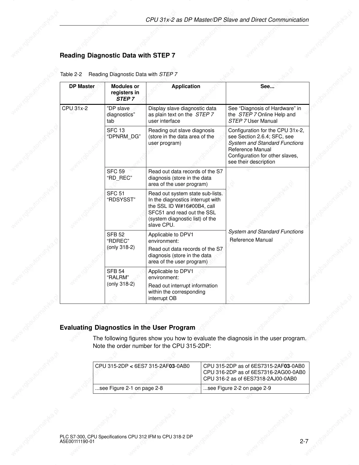
Reading Diagnostic Data with STEP 7
Table 2-2 Reading Diagnostic Data with STEP 7
DP Master
Modules or
registers in
STEP 7
Application See...
CPU 31x-2 ”DP slave
diagnostics”
tab
Display slave diagnostic data
as plain text on the STEP 7
user interface
See “Diagnosis of Hardware” in
the STEP 7 Online Help and
STEP 7 User Manual
SFC 13
“DPNRM_DG”
Reading out slave diagnosis
(store in the data area of the
user program)
Configuration for the CPU 31x-2,
see Section 2.6.4; SFC, see
System and Standard Functions
Reference Manual
Configuration for other slaves,
see their description
SFC 59
“RD_REC”
Read out data records of the S7
diagnosis (store in the data
area of the user program)
SFC 51
“RDSYSST”
Read out system state sub-lists.
In the diagnostics interrupt with
the SSL ID W#16#00B4, call
SFC51 and read out the SSL
(system diagnostic list) of the
slave CPU.
SFB 52
“RDREC”
(only 318-2)
Applicable to DPV1
environment:
Read out data records of the S7
diagnosis (store in the data
area of the user program)
System and Standard Functions
Reference Manual
SFB 54
“RALRM”
(only 318-2)
Applicable to DPV1
environment:
Read out interrupt information
within the corresponding
interrupt OB
Evaluating Diagnostics in the User Program
The following figures show you how to evaluate the diagnosis in the user program.
Note the order number for the CPU 315-2DP:
CPU 315-2DP < 6ES7 315-2AF03-0AB0 CPU 315-2DP as of 6ES7315-2AF03-0AB0
CPU 316-2DP as of 6ES7316-2AG00-0AB0
CPU 316-2 as of 6ES7318-2AJ00-0AB0
...see Figure 2-1 on page 2-8 ...see Figure 2-2 on page 2-9
 Loading...

