Cycle and Reaction times
3-8
PLC S7-300, CPU Specifications CPU 312 IFM to CPU 318-2 DP
A5E00111190-01
PROFIBUS-DP interface
In the case of the CPU 315-2 DP/316-2DP, the cycle time is typically extended by
5% when the PROFIBUS-DP interface is used.
In the case of the CPU 318-2, there is no increase in cycle time when the
PROFIBUS-DP interface is used.
Integrated Functions
With CPU 312-IFM and 314-IFM operation the cycle time increases by a maximum
of 10% when using integrated functions. Also take into consideration a possible
instance DB update during the cycle checkpoint.
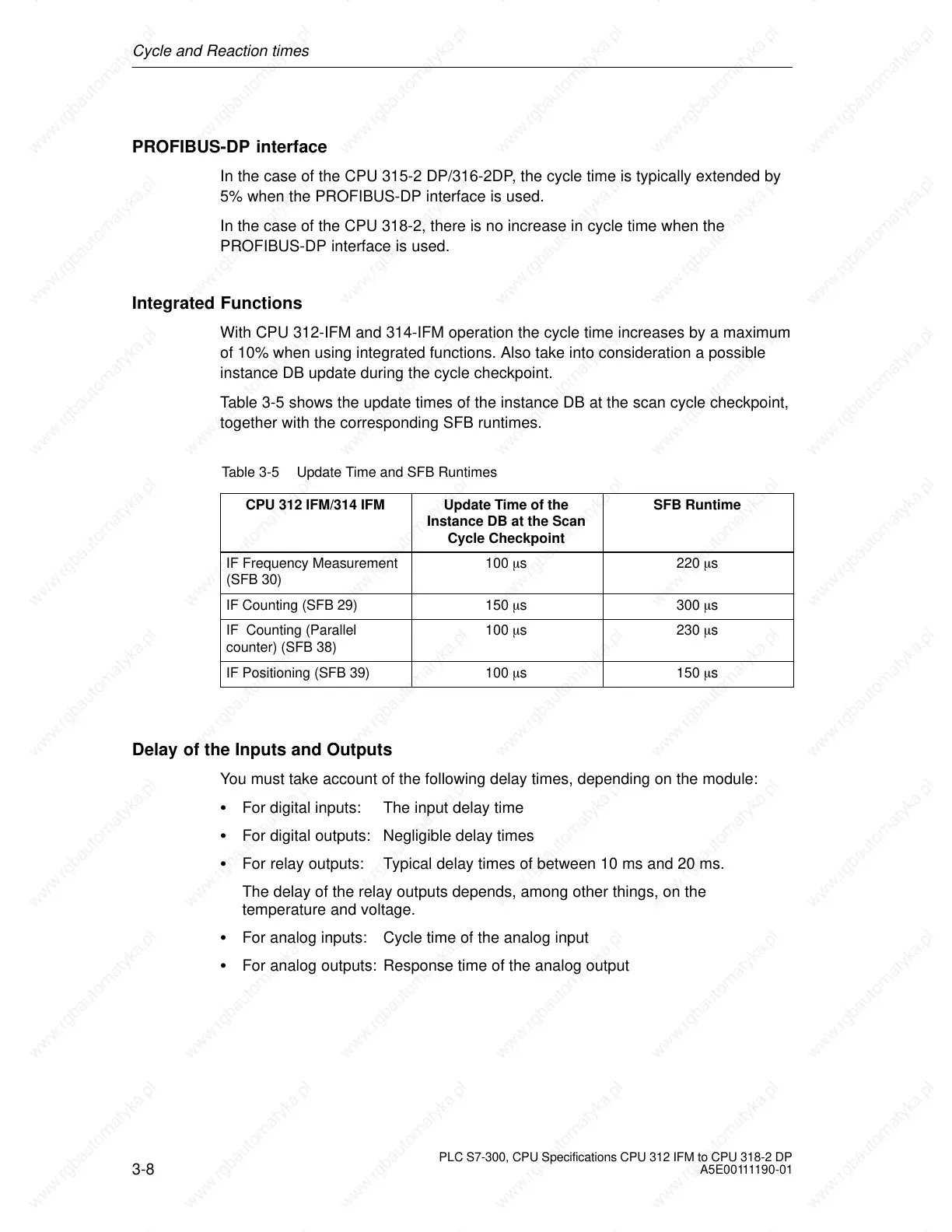
Table 3-5 shows the update times of the instance DB at the scan cycle checkpoint,
together with the corresponding SFB runtimes.
Table 3-5 Update Time and SFB Runtimes
CPU 312 IFM/314 IFM
Update Time of the
Instance DB at the Scan
Cycle Checkpoint
SFB Runtime
IF Frequency Measurement
(SFB 30)
100 s 220 s
IF Counting (SFB 29) 150 s 300 s
IF Counting (Parallel
counter) (SFB 38)
100 s 230 s
IF Positioning (SFB 39) 100 s 150 s
Delay of the Inputs and Outputs
You must take account of the following delay times, depending on the module:
For digital inputs: The input delay time
For digital outputs: Negligible delay times
For relay outputs: Typical delay times of between 10 ms and 20 ms.
The delay of the relay outputs depends, among other things, on the
temperature and voltage.
For analog inputs: Cycle time of the analog input
For analog outputs: Response time of the analog output
 Loading...

