CPUs
1-2
PLC S7-300, CPU Specifications CPU 312 IFM to CPU 318-2 DP
A5E00111190-01
1.1 Control and Display Elements
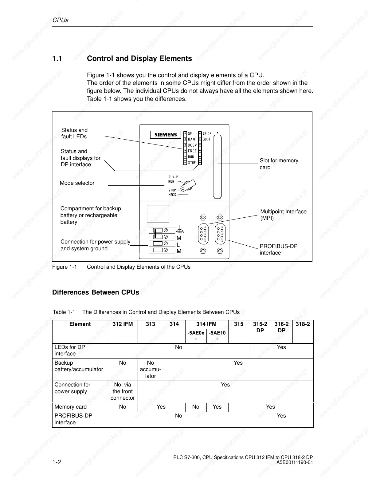
Figure 1-1 shows you the control and display elements of a CPU.
The order of the elements in some CPUs might differ from the order shown in the
figure below. The individual CPUs do not always have all the elements shown here.
Table 1-1 shows you the differences.
Slot for memory
card
Compartment for backup
battery or rechargeable
battery
M
L
+M
PROFIBUS-DP
interface
Status and
fault LEDs
Mode selector
Connection for power supply
and system ground
Multipoint Interface
(MPI)
Status and
fault displays for
DP interface
Figure 1-1 Control and Display Elements of the CPUs
Differences Between CPUs
Table 1-1 The Differences in Control and Display Elements Between CPUs
Element 312 IFM 313 314
314 IFM
315 315-2 316-2 318-2
-5AE0x
-
-5AE10
-
DP DP
LEDs for DP
interface
No Yes
Backup
battery/accumulator
No No
accumu-
lator
Yes
Connection for
power supply
No; via
the front
connector
Yes
Memory card No Yes No Yes Yes
PROFIBUS-DP
interface
No Yes
 Loading...

