CPU 31x-2 as DP Master/DP Slave and Direct Communication
2-30
PLC S7-300, CPU Specifications CPU 312 IFM to CPU 318-2 DP
A5E00111190-01
As of byte x +4
The purpose of the bytes beginning with byte x+4 depends on byte x+1 (see
Figure 2-8).
Byte x+1 Contains the Code for...
Diagnostic Interrupt (01
H
) Hardware interrupt (02
H
)
The diagnostic data contains the 16 bytes of
status information from the CPU. Figure 2-9
shows the contents of the first four bytes of
diagnostic data. The next 12 bytes are always
0.
You can freely program 4 interrupt information
bytes for the process interrupt. In STEP 7,
transfer these bytes with SFC 7 “DP_PRAL”
to the DP Master
(refer to Chapter 2.6.10).
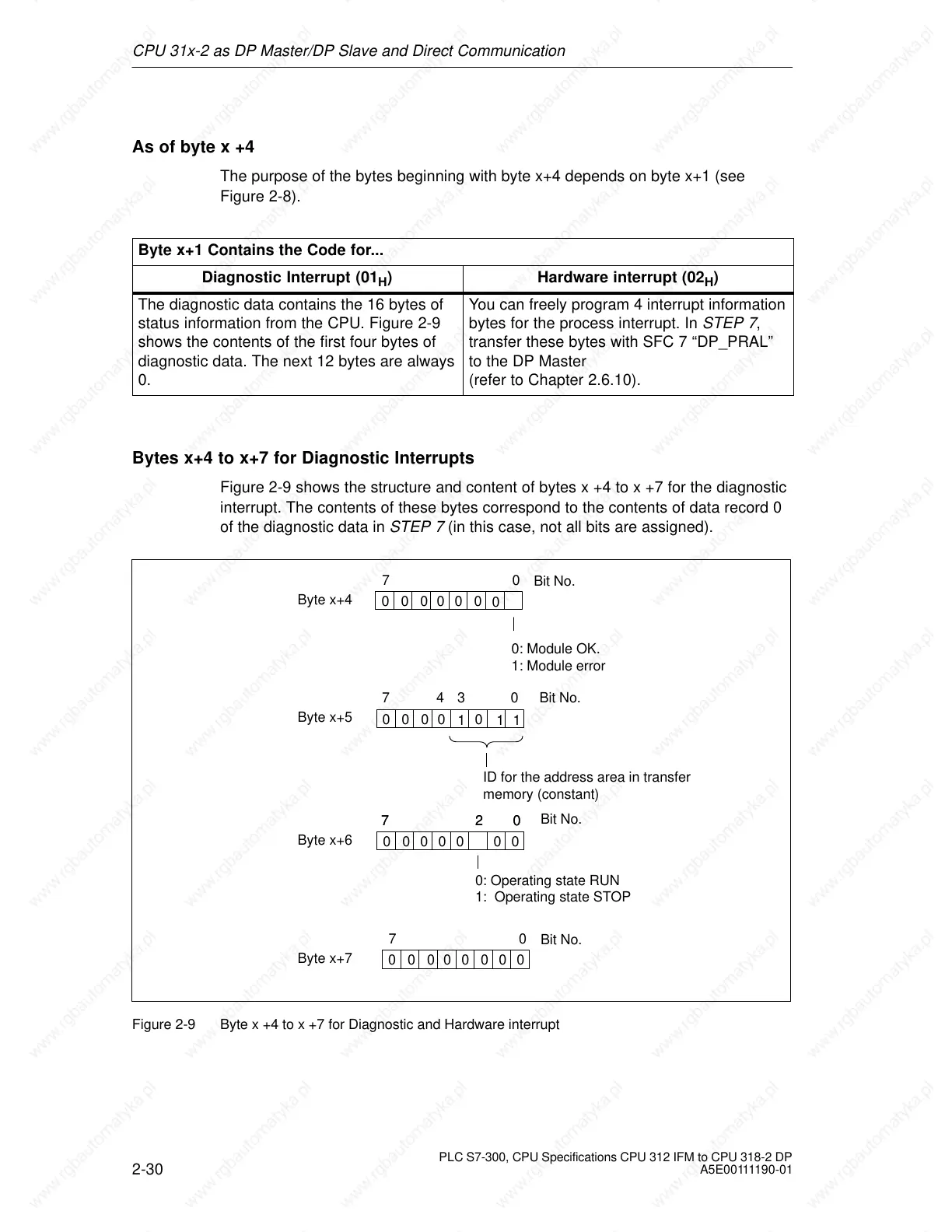
Bytes x+4 to x+7 for Diagnostic Interrupts
Figure 2-9 shows the structure and content of bytes x +4 to x +7 for the diagnostic
interrupt. The contents of these bytes correspond to the contents of data record 0
of the diagnostic data in STEP 7 (in this case, not all bits are assigned).
Byte x+4
70
Bit No.
Byte x+5
Byte x+6
0: Operating state RUN
1: Operating state STOP
0: Module OK.
1: Module error
0
1
000 0
1
74 0
02
3 Bit No.
Bit No.
7
02
7
0
0
00000
1
ID for the address area in transfer
memory (constant)
0000000
Byte x+7
70
Bit No.
00000000
Figure 2-9 Byte x +4 to x +7 for Diagnostic and Hardware interrupt
 Loading...

