LMV Series Technical Instructions
Document No. LV3-1000
SCC Inc. Page 13 Section 5
NOTE: The total time of the standardization shown in Figure 5-3 is 70 seconds with a VFD ramp time
of 30 seconds. Longer VFD / LMV3 ramp times will increase the total time taken for the
standardization.
NOTE: The VFD in the example above is spanned so 10 VDC = 62 Hz. Thus, 9.5 VDC is approximately 60
Hz.
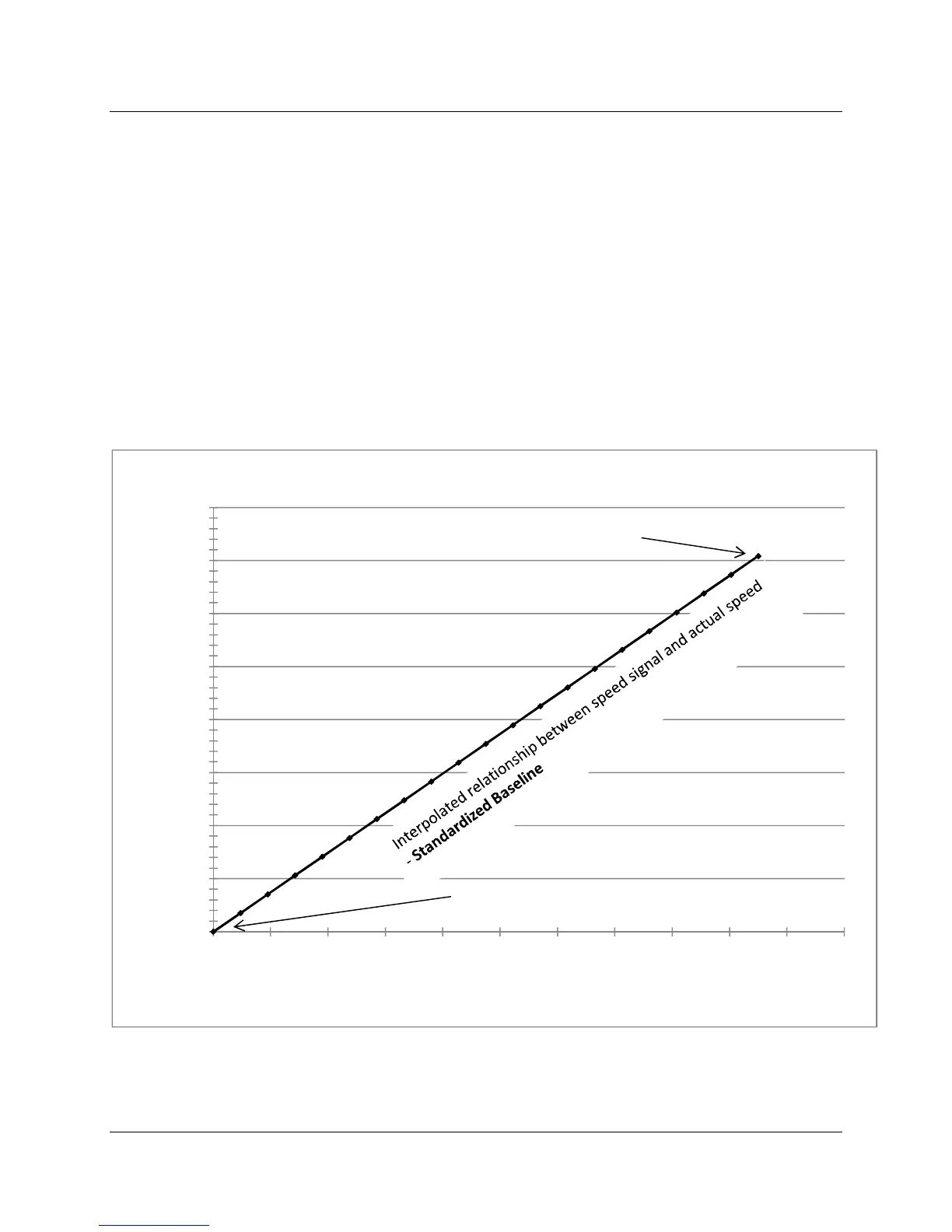
Based off of the RPM that was read at 9.5 VDC (in this case 3544 RPM) and an assumption of 0 RPM at
minimum signal (0 VDC), a two point linear interpolation is automatically done by the LMV3, which
establishes the linear relationship between the speed signal and the blower RPM.
In fact, this relationship is the slope of the line with a 0 intercept, and is defined with an equation. This
equation states that for every 1 VDC increase in speed signal, the blower speed should increase by
373.05 RPM. This relationship is shown in Figure 5-4.
Figure 5-4: Result of Standardization (2-Pole Blower Motor) and Interpolation
y = 373.05x
0
500
1000
1500
2000
2500
3000
3500
4000
0.00 2.00 4.00 6.00 8.00 10.00
Blower Speed (RPM)
Speed Signal to VSD (VDC)
Result of Standardization
Near max speed point for interpolation
(3544 RPM @ 9.5 VDC)
Minimum point for Interpolation (0 RPM @ 0 VDC)

 Loading...


