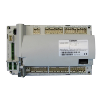
LMV Series Technical Instructions
Document No. LV3-1000
SCC Inc. Page 23 Section 5
Suggested Setup Procedure for the VSD Speed Shift
The LMV3 also features a VSD speed shift, which enables the VSD speed curve to be shifted up or down
a limited amount at any point on the fuel-to-air ratio control curve. This feature enables the LMV3 to
accept a 4-20mA signal from an external device to shift the VSD speed, which “trims” the fuel-to-air
ratio.
This VSD speed shift is typically used to trim the fuel-to-air ratio in response to burner intake air
temperature and / or %O
2
in the burner exhaust. Taking this into consideration, an external controller
that reads burner intake air temperature and / or %O
2
in the burner exhaust and outputs a 4-20mA
signal to the LMV3 is typically used to command the VSD speed shift. Hard limits on the VSD speed shift
are programmable in the LMV3 so that a partial or complete failure of the 4-20mA signal will not cause
an unsafe fuel-to-air ratio.
The 4-20mA signal can also be used to shift the ignition speed of the VSD, so that the ignition point can
be made richer or leaner if desired.
The following pages detail how to set up and use the VSD speed shift on the LMV3.
Prerequisites
• If the 4-20mA analog input is employed for speed shift, it cannot be used for load control. When the
4-20mA signal is employed for speed shift, the firing rate command must be sent to the LMV3 in a
different way. For the LMV36, the firing rate must be controlled via Modbus. For the LMV37, the
firing rate must be controlled via Modbus or a floating bumping (3 point) signal.
• The fuel-to-air ratio control curves must be fully commissioned (see Section 4 – Commissioning)
before the VSD speed shift is activated. Care must be taken to allow for enough “room” at P1 and at
P9 for the VSD speed shift. For example, if +/- 10% VSD speed shift will be used, P1 low fire cannot
be lower than 20% VSD (10% is the absolute minimum setting for the VSD) and P9 high fire cannot
be higher than 90% VSD (100% is the absolute maximum setting for the VSD).
• When commissioning the fuel-to-air ratio control curves, a linear increase in fuel flow from low fire
(P1) to high fire (P9) is highly recommended, especially if the VSD speed shift will be used for O
2
trim.

 Loading...


