LMV Series Technical Instructions
Document No. LV3-1000
SCC Inc. Page 7 Section 4
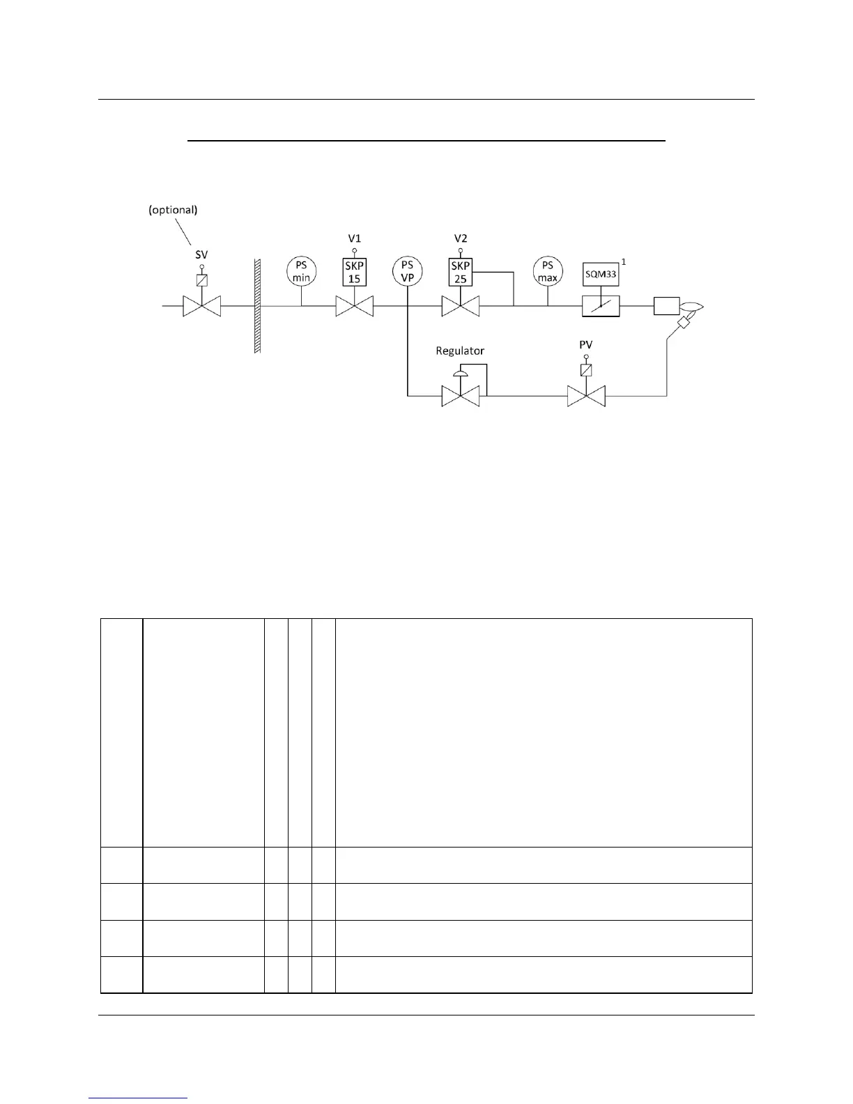
Modulating Gas - Pilot Ignition 1 (Pilot between V1 and V2)
(Fuel Train Options 2, 8, 15, 20)
Legend:
Safety valve (optional, outside building)
Upstream gas valve (main)
Downstream gas valve (main)
Notes:
1. Fuel actuator not used with options 8 or 15
2. The SKP25 (on valve V2) is typically replaced by an SKP55/75 for pneumatically linked gas trains
Operating Mode
Parameter 201 (fuel 0) or 301 (fuel 1)
VSD Speed Feedback (if activated)
Description
2 Gp1 mod • • •
Modulating gas, pilot ignition 1 (pilot between V1 and V2), electronically
linked fuel-to-air ratio
Modulating gas, pilot ignition 1 (pilot between V1 and V2), pneumatically
linked fuel-to-air ratio
Modulating gas, pilot ignition 1 (pilot between V1 and V2), pneumatically
linked fuel-to-air ratio, no actuators
Modulating gas, pilot ignition 1 (pilot between V1 and V2), electronically
linked fuel-to-air ratio

 Loading...


