LMV Series
Technical Instructions
Document No. LV3-1000
SCC Inc. Page 1 Section 3
Section 3: Parameters
T
he Siemens LMV3 has a number of parameters that can be adjusted to suit the wide variety of
applications that exist in the burner / boiler and industrial heating market.
These parameters are broken up into three main groups by password access:
User Level access does not require a password, and encompasses all of the parameters that an
end user might have to view or adjust during the life of the burner / boiler.
Service Level access does require a password, and encompasses all of the user level parameters,
plus additional parameters that a service technician might need to access to tune or
maintain the burner / boiler.
OEM Level access requires a different password than the service level, and enables the OEM to
access all available parameters, including safety-related parameters.
The parameters on the LMV3 are organized into groups of 100. Each group of 100 is described below:
100: General information / configuration / Modbus
2
00: Settings specific to fuel 0
300: Settings specific to fuel 1 (LMV36 only)
400: Fuel-air ratio curves
Special positions / modulation
ramps / VSD speed shift
6
00: Actuators and VSD configuration
700: Fault history
800: N/A
900: Operational data
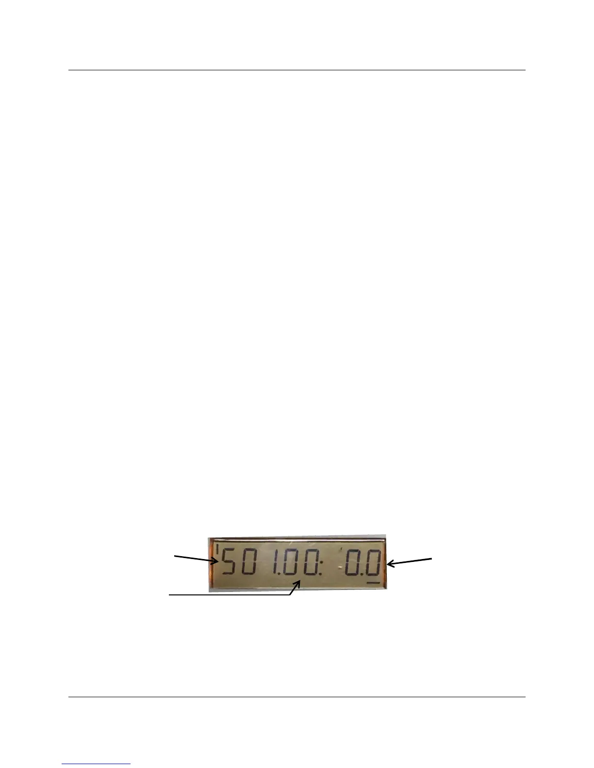
Some parameters have multiple indexes. For example, parameter 501 will initially display as 501:00
(index 0), but can be changed to 501:01 (index 1) or 501:02 (index 2). To move between indexes, use
the following procedure:
When first accessing parameter 501, 501:00 will display. The “501” will be flashing. Press the ENTER
key once, and the “00” will begin flashing. Press the + or – key to move between the various indexes. In
order to change the value stored in an index, press ENTER again and use the + or – key to change the
value. Once the correct value is displayed, press ENTER to store it.
Figure 3-1: LMV3 Parameter Example with Indexes
Every LMV3 parameter is described thoroughly in the following LMV3 parameter list. After the
parameter list, sequence diagrams for each fuel train available in the LMV3 are provided. For an
example of what each of these fuel trains looks like, see Section 4.

 Loading...


