LMV Series Technical Instructions
Document No. LV3-1000
SCC Inc. Page 9 Appendix A
Low Fire Hold with an RWF55 (continued)
Procedure – Steam Boiler with an RWF55 with Analog Output
In the case of steam boilers, temperature sensors located in the boiler water jacket are
recommended. Technical Instructions SEN-1000 provides additional information on
temperature sensors.
1. Do the following:
On an LMV37 only: Place a jumper between terminals X5-03.2 and X5-03.4.
On an LMV36 only: Set parameter 204 to 2. If 2 is not an option (older
LMV36s), set parameter 204 to 0.
2. Set the following parameters in the RWF55:
ConF > Inp > Inp1 > SEn1 = signal type of pressure sensor
ConF > Inp > Inp1 > SCL1 = 0
ConF > Inp > Inp1 > SCH1 = high end of the range of the pressure sensor
ConF > Inp > Inp3 > SEn3 = type of RTD being used for a belly sensor
ConF > Inp > Inp3 > dF3 = 0
ConF > Cntr > CtYP = 2
ConF > AF > FnCt = 11
ConF > AF > AL = temperature to enable low fire hold
ConF > AF > HYSt = deadband around low fire hold temperature
ConF > OutP > FnCt = 4
ConF > OutP > SiGn = 1
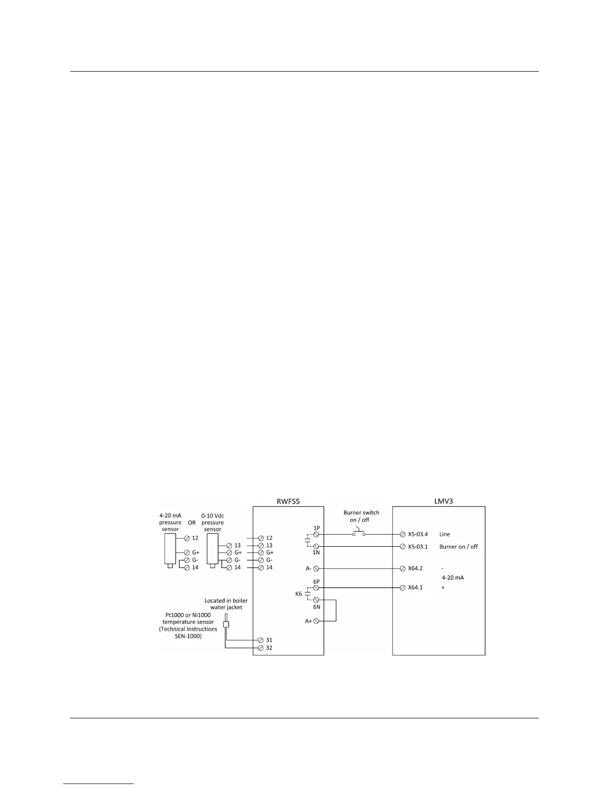
3. Wire the LMV3 and RWF55 as shown in Figure 3:
Figure 3: Low Fire Hold via Analog Output on a Steam Boiler
See page 19 for an example of the low fire hold operation.

 Loading...


