Technical Instructions LMV Series
Document No. LV3-1000
Section 4 Page 14 SCC Inc.
4. If a VSD is being used, activate it by setting parameter 542 to 1. Otherwise, leave parameter 542
set to 0.
NOTE: Depending on the direction of rotation and home position set in the LMV3, the actuator
may rotate as soon as the fuel train is selected. For this reason, it is highly recommended that the
actuator shaft be uncoupled from the valve / damper until the parameters pertaining to the
direction of rotation and home position are set.
5. For each actuator connected, set the direction of rotation via parameters 602 and 609.
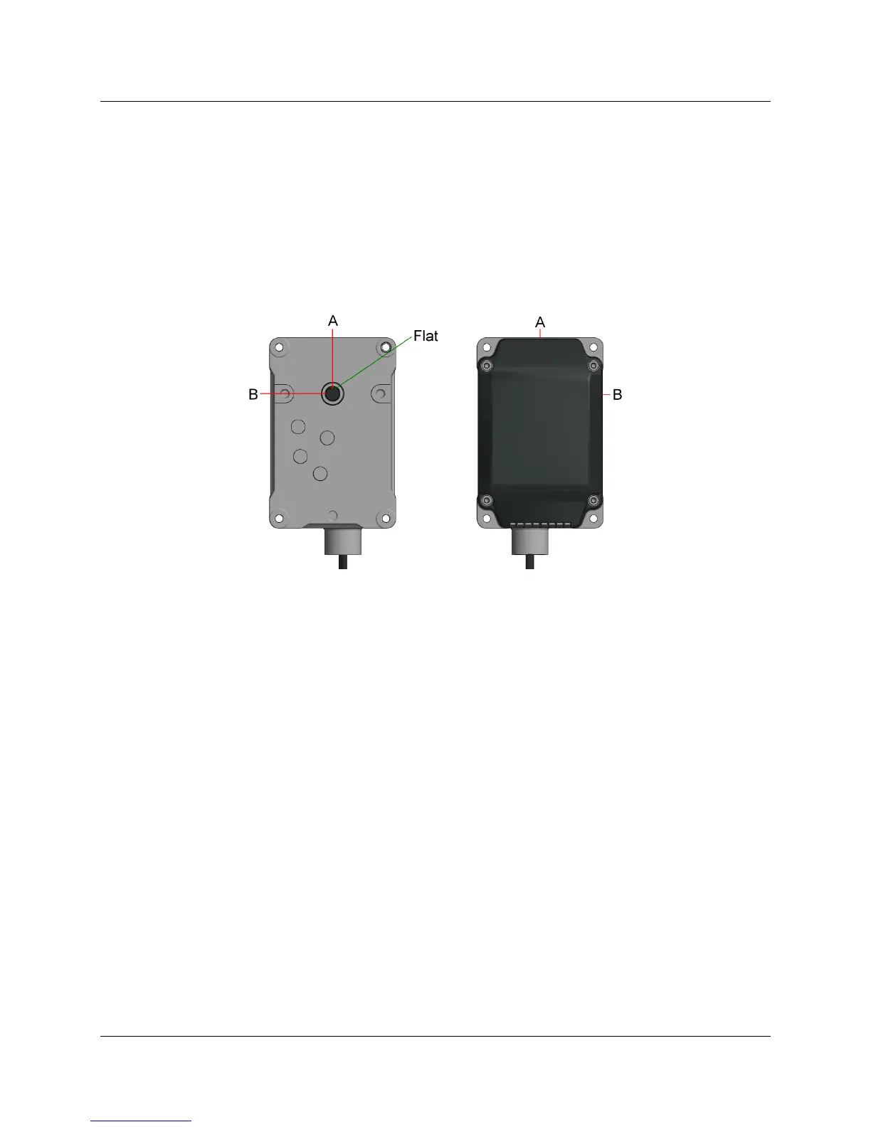
Figure 4-3: Counterclockwise vs. Clockwise Rotation
a. Counterclockwise Rotation - Flat is perpendicular to line A when indicated actuator
position is at 0°. Flat will be perpendicular to line B when indicated actuator position is
90°. This is how the actuator's shaft comes from the factory.
b. Clockwise Rotation - Flat is perpendicular to line B when indicated actuator position is
at 0°. Flat will be perpendicular to line A when indicated actuator position is 90°.
6. Set actuator home (standby) positions if necessary via parameters 501-506. Defaults are 0° and
0% VSD. For dual fuel burners this will need to be done for both fuels.
7. Set the actuator reference direction. All SQM33… actuators have a range of motion from 0-90°
during operation. However, before every startup, each actuator connected must rotate the
shaft to either a position less than 0° or a position greater than 90° to reference the actuator
shaft position. Rotating to a position less than 0° is called referencing on the “closed” side.
Rotating to a position greater than 90° is called referencing on the “open” side. See Figure 4-4
for more details.

 Loading...


