LMVSeriesTechnicalInstructions
DocumentNo.LV3‐1000
SCCInc. Page1 Section2
2‐1:WiringIntroduction
The LMV3 is a very flexible burner control.As such, there are many different ways to wire it.The
specificapplicationwilldictatethewiringrequired.Thissectiondetailsthemostcommonapplications.
The parameter settings outlined in Section 3 can enable, disable, or change the functionality of many
terminals on
the LMV3.Thus, wiring and parameter settings work together to make the LMV3 an
extremelyversatileBMS.
Thissectionincludesterminaldescriptions(Sections2‐2and2‐3)andextensivewiring diagrams(Section
2‐4)thatdetailthemanyapplicationsoftheLMV3.
Terminals
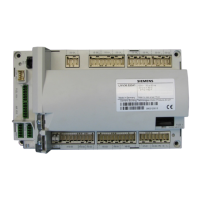
The connection terminals of the
LMV3 are white RAST 5 and green RAST 3.5 connectors (plugs).Line
voltage plugs are keyed so they will only fit into one specific socket of the LMV3, eliminating the
possibilityofinsertingaplugintoanincorrectsocket.
Each plugis designed toconnect one external deviceor a
smallgroup of externaldevices, such asgas
valves,to theLMV3.Each groupofplugs onthe frontof theLMV3 providesline voltage,neutral,and
protectiveearthgroundsoanadditionalterminalstripisnotnecessary.
Note: Allprotectiveearthgrounds(PE),neutrals(N),andlines(L)arecommon
insidetheLMV3.
X9‐ 01. 04
PlugGroup PlugNumberinGroup PinNumberonPlug
Figure2‐1.1:NumberingSchemeonWhiteLineVoltage(RAST5)TerminalsoftheLMV3
Note:Dashesordotscanbeusedinterchangeablybetweenthenumbersshownabove.
X62. 2
PlugNumber PinNumber
Figure2‐1.2:NumberingSchemeonGreenLowVoltage(RAST3.5)TerminalsoftheLMV3
Terminal descriptions (Sections 2‐2 and 2‐3) provide a map outlining exactly where the line and low
voltageplugsarelocated.
Foreachplug,Pin1ismarkedonthecasingoftheLMV3.

 Loading...


