Technical Instructions LMV Series
Document No. LV3-1000
Section 5 Page 18 SCC Inc.
Looking at the blower speed monitoring bands in Figure 5-5, and also the standardized speed baseline
shown in Figure 5-4, it is clear that the LMV3 expects the VSD blower to have a linear response through
the operating range. However, no VSD blower will have a perfectly linear response. The next section
will illustrate how linear VSD blower response must be to have trouble-free operation.
Blower Speed Response during Operation
As was mentioned in the last section, the LMV3 expects the VSD blower to have a linear relationship
between the speed signal and the actual speed. For a 9.5 VDC speed signal and a 3544 RPM
standardized speed (as seen in the examples above) this relationship is precisely y = 373.05x where x is
the signal and y is the RPM. On real VSD blowers, it is not practical for the relationship to be perfectly
linear, so the LMV3 has adjustable tolerance bands and adjustable timings for these bands to deal with
some non-linearity between the speed signal and the actual speed.
Assuming that the VSD blower is programmed to have a linear response to the speed signal, the main
source of non-linearity is ramping the blower speed up and down. The faster the ramp rates (shorter
times) the more difficult it is for the VSD blower to keep a linear response. This is mostly due to the
inertia of the rotating parts in the motor and blower. Slower ramp rates (longer times) will help
minimize the inertia effects of the blower, especially when ramping down. Electronic breaking is very
helpful when attempting to ramp down a high inertia motor and blower combination quickly.
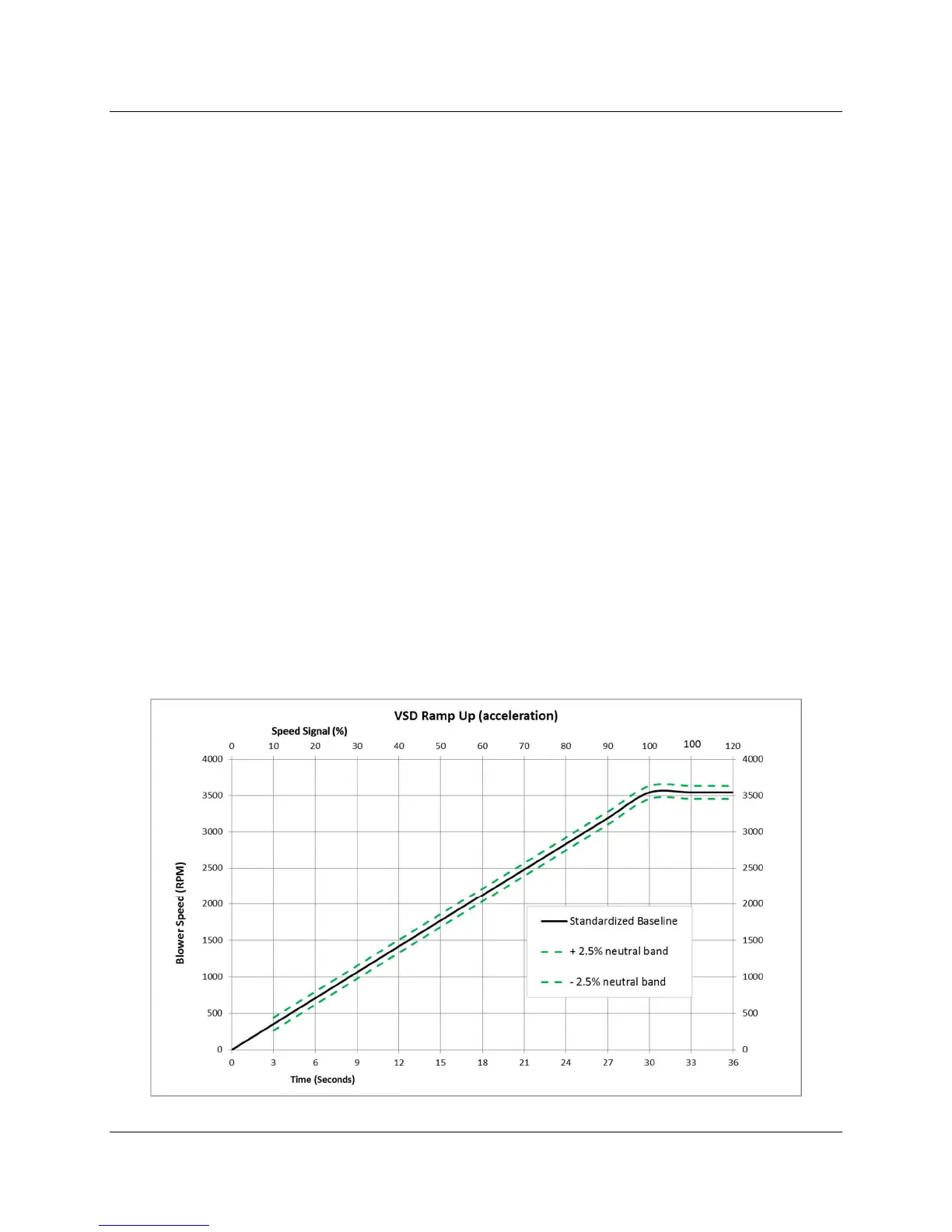
Figure 5-6 below shows a typical VSD blower ramping up during operation (accelerating). The dashed
lines represent the borders of the neutral zone, set by parameter 662. A setting of 2.5% is shown below,
which will yield a neutral band of +/- 2.5% or 5% total. These percentages are of the standardized
speed, so in absolute terms 2.5% * 3544 = +/- 89 RPM or 177 RPM total neutral band, at all VSD speeds
from 10% to 100%.
Figure 5-6: VSD Blower Speed Response during Acceleration

 Loading...


