Connecting
6.5 Signaling contact
SCALANCE X-300
140 Operating Instructions, 02/2012, A5E01113043-12
6.5 Signaling contact
6.5.1 24 VDC signaling contact
The signaling contact is connected to a 2-pin plug-in terminal block.
The signaling contact can be subjected to a maximum load of 100 mA (safety extra low
voltage SELV 12 VDC / 24 VDC).
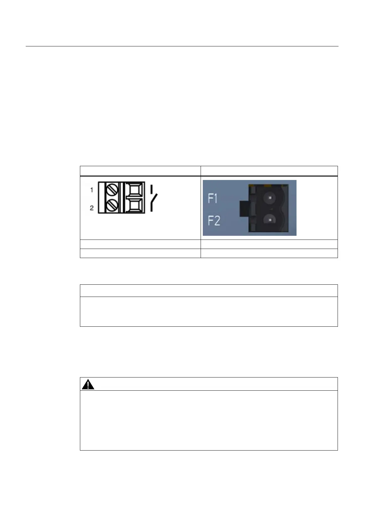
Table 6- 8 Pin assignment of the signaling contact
Pin number Assignment (example)
Pin 1 F1
Pin 2 F2
To wire up the signaling contact, use a copper cable of category 18-12 AWG or cable with a
cross-section of 0.75 to 2.5 mm².
CAUTION
Laying the connecting cables of the signaling contact with the X-300EEC
To improve the EMC properties (surge protection), the two connecting cables of the
signaling contact should be laid together.
6.5.2 Signaling contact 100 to 240 VAC / 60 to 250 VDC (X-300EEC)
WARNING
Danger from line voltage
Devices with this mark have a 100 to 240 VAC power supply.
This product can only function correctly and safely if it is transported, stored, set up, and
installed correctly, and operated and maintained as recommended.
Connecting and disconnecting may only be performed by an electrical specialist.
Connect or disconnect power supply cables only when the power is turned off.
 Loading...