Home
Siemens
Circuit breakers
SENTRON 3VA2
Siemens SENTRON 3VA2 User Manual
5
of 1
of 1 rating
676 pages
Give review
Manual
Specs
To Next Page
To Next Page
To Previous Page
To Previous Page
Loading...
Tec
hnical specif
ications
6.4
Der
ating and t
emperatur
e compensat
ion
3VA
mold
e
d cas
e c
ircui
t br
eak
ers
wit
h IE
C cer
tif
ic
ate
Manu
al
,
03/
2019
,
A5E
0360
31770
10
-
03
627
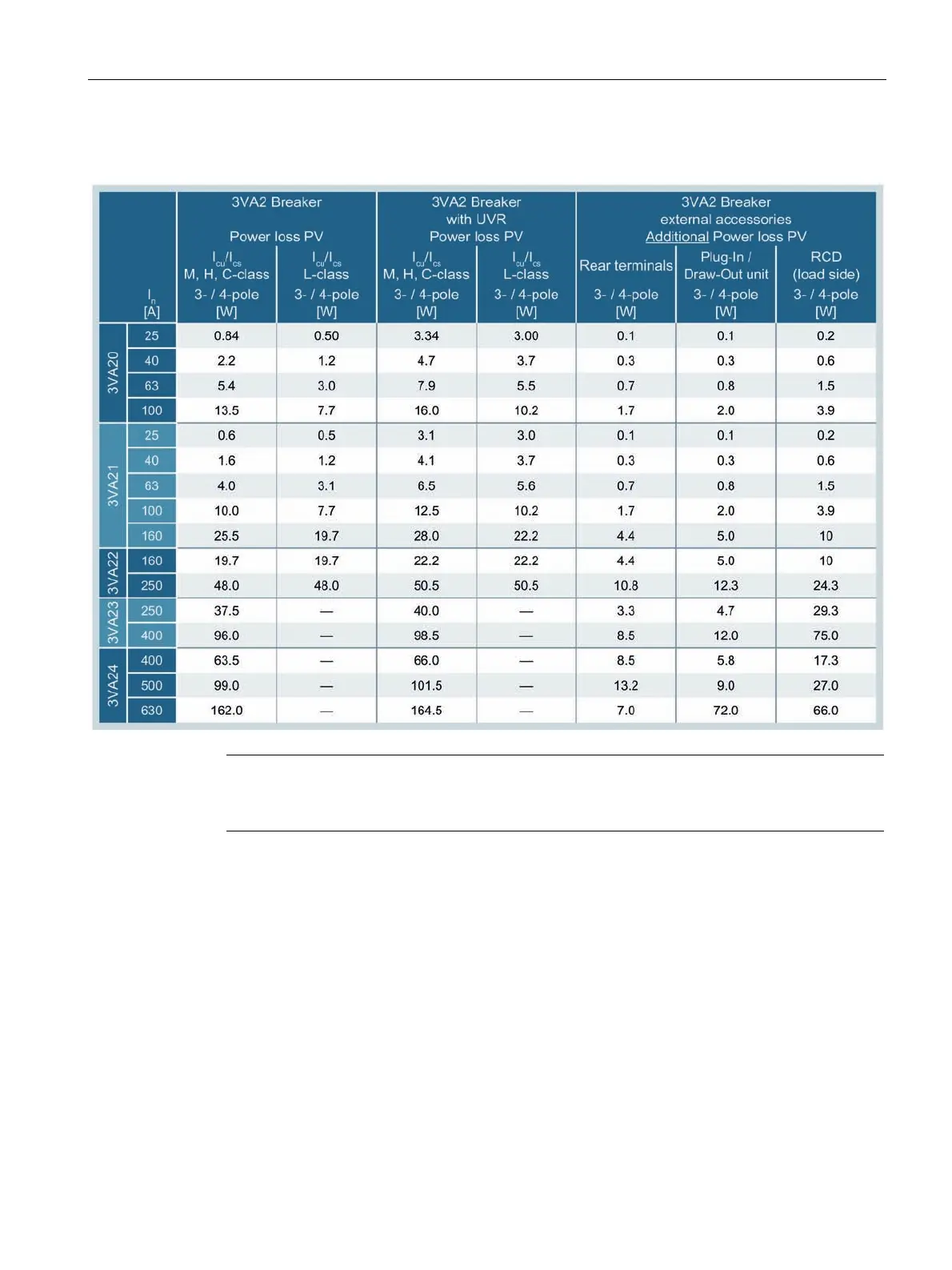
6.3.2
Power los
ses of 3VA2 molded
case circuit b
reakers
Note
The spec
ified power loss
applies to 3
-
pole and 4
-
pole devic
es in the cas
e o
f
3
-
phase,
symm
etrical loading.
628
630
Table of Contents
Table of Contents
5
Introduction
11
About this Documentation
11
Product-Specific Information
12
Target Readers
12
Technical Support
12
Reference Documents
12
Description
15
Overview - Applications and Portfolio
15
Applications and Possible Uses
16
Portfolio
18
Application Examples
22
Detailed Information about Applications and Possible Uses
24
Technical Specifications
26
Molded Case Circuit Breakers and Accessories in the System
30
Ergonomic Design
32
The Right Circuit Breaker for any Installation Conditions
33
Ergonomic Design of Circuit Breakers, Handles and Control Elements
36
Wide Range of Accessories
39
Connection Technology
41
Technical Details
43
Circuit Breaker Identification
44
Operation
48
Design and Components - 3VA1
49
Design and Components - 3VA2
50
Current Limitation
51
Breaking Capacity
53
Infeed
54
Selectivity
55
Standards and Guidelines
59
Compliance with Standards
59
Electromagnetic Compatibility
59
Certificates
60
Ambient Conditions
60
Permissible Mounting Positions and Mounting Positions with Accessories
62
Safety Clearances
63
Arcing Spaces
69
Degrees of Protection
70
Environmental Protection
70
Protection System
71
Description of Functions
72
Characteristic Curves
74
Guide to Setting the Tripping Characteristic
75
Overload Protection (L)
77
Short-Time Delayed Short-Circuit Protection (S)
78
Instantaneous Short-Circuit Protection (I)
78
Ground-Fault Protection (G)
78
Neutral Conductor Protection (N)
81
Zone Selective Interlocking (ZSI)
84
Thermal-Magnetic Trip Unit
87
Thermal Trip Unit (L)
87
Magnetic Trip Unit with Short-Circuit Protection (I)
87
Application Cases and Trip Unit Types
88
Electronic Trip Unit
89
Connections
91
Protection Functions
92
Operator Controls
95
Load Acceptance and Load Shedding - Load Management
104
Measuring with a Rogowski Coil
105
Applications
111
3VA IEC Trip Units
111
Line Protection Applications of 3VA Molded Case Circuit Breakers
112
Variants
113
Thermal-Magnetic Trip Units
113
Electronic Trip Units
117
Overview of 3VA Molded Case Circuit Breakers in Line Protection Applications
142
Motor Protection Applications of 3VA Molded Case Circuit Breakers
146
3VA Molded Case Circuit Breakers for Starter Protection
147
3VA Molded Case Circuit Breakers for Motor Protection
150
3VA2 Motor Protection Circuit Breaker up to 500 A, Tested According to IEC en 60947-4-1
151
3VA2 Motor Protection Breaker as Tested Motor Protection Combination, 3VA2 with 3RT
152
Protection Functions of 3VA2 Molded Case Circuit Breakers for Motor Protection
152
ETU350M Electronic Trip Unit
157
5-Series and 8-Series Electronic Trip Units
160
ETU550M Electronic Trip Unit
161
ETU860M Electronic Trip Unit
163
Use of 3VA1 Molded Case Circuit Breakers as Switch Disconnectors
167
Overview of 3VA1 as Switch Disconnectors
171
Upstream Protection of Switch Disconnectors
172
DC Network Applications of 3VA Molded Case Circuit Breakers
174
Variants
175
Breaking Capacity with Direct Current
176
Recommended Circuit Configurations for DC Systems
177
Applications of the 3VA Molded Case Circuit Breaker with Frequency Converters
179
400 Hz Network Applications of 3VA Molded Case Circuit Breakers
181
IT System Applications of 3VA Molded Case Circuit Breakers
183
Selection Criteria for 3VA Molded Case Circuit Breakers
183
Fault Situation
184
Safety-Related Applications of 3VA Molded Case Circuit Breakers
185
Accessories
187
Overview of Accessories for 3VA Molded Case Circuit Breakers
187
Accessories Groups
187
Possible Combinations of of Accessories
188
Internal Accessories
193
Mounting Locations on 3VA Molded Case Circuit Breakers
193
Auxiliary and Alarm Switches
199
Contact Sequence Diagrams
203
Technical Specifications of Auxiliary and Alarm Switches
204
Auxiliary Releases
206
Time-Delay Devices for Undervoltage Releases
211
COM060 Communication Module
211
Module
212
Connection System
213
General Information about Cables and Busbars
213
Portfolio of Connection Components for 3VA Molded Case Circuit Breakers
216
General Overview
216
Front Cable Connection
220
Front Busbar and Cable Lug Connections
234
Rear Busbar and Cable Lug Connections
241
Further Connection Accessories
248
Insulating Measures
248
Auxiliary Conductor Terminal
271
Plug-In and Draw-Out Technology
274
Introduction
274
Overview of Variants / Products
277
General Information
278
Information about Installation, Built-On and Built-In Components
279
Plug-In Technology
280
Product Description
280
Combination with Other Accessories
286
Draw-Out Technology
287
Product Description
287
Combination with Other Accessories
297
Accessories for Plug-In and Draw-Out Units
297
Description of Individual Product Variants
297
Overview of Technical Specifications
309
Combination with Other Accessories
310
Manual Operators
311
Opening, Closing and Resetting the 3VA Molded Case Circuit Breaker
312
Front Mounted Rotary Operator
314
Door Mounted Rotary Operator
318
Side Wall Mounted Rotary Operator
324
Locking and Interlocking for Manual Operators
326
Locking by the Handle
326
Locking and Interlocking by the Rotary Operator
328
Degree of Protection
331
Accessories
332
Motor Operators
333
MO310 Side Mounted Motor Operator
333
MANUAL, AUTO and LOCK Modes
336
Closing, Opening and Resetting the 3VA Molded Case Circuit Breaker
338
Faults, Causes of Faults and Rectification of Faults
340
Motor Operator MO320
341
MANUAL, AUTO and LOCK Modes
343
Opening, Closing and Resetting the 3VA Molded Case Circuit Breaker
344
Faults, Causes of Faults and Rectification of Faults
348
SEO520 Motor Operator with Stored Energy Operator
349
MANUAL, AUTO and LOCK Modes
351
Closing, Opening and Resetting the 3VA Molded Case Circuit Breaker
352
Faults, Causes of Faults and Rectification of Faults
355
Communication
356
Accessories
357
Technical Specifications
359
Locking and Interlocking
362
General Information
362
Locking
362
Interlocking
363
Locking
365
Padlock Device for the Handle
365
Cylinder Locks for Locking the 3VA Molded Case Circuit Breaker
367
Front Interlocking
371
Cylinder Locks for Implementing Interlocks between Multiple 3VA Molded Case Circuit Breakers
371
Sliding Bar with Bowden Cable: Modules for Sliding Bar with Bowden Cable
376
Sliding Bar
379
Rear Interlock
381
Residual Current Devices
388
Portfolio
388
Possible Combinations of Residual Current Devices and 3VA Circuit Breakers
396
Residual Current Devices for Mounting on Circuit Breakers
397
Side Mounted Residual Current Devices Basic RCD310 and Basic RCD510
399
Loadside Residual Current Devices Basic RCD320 and Basic RCD520
417
Loadside Residual Current Device Basic RCD520B
430
Loadside Residual Current Device Advanced RCD820
454
Special Operating Modes of Residual Current Devices
471
Technical Specifications
474
Modular Residual Current Device
480
Communication and System Integration
486
System Description
486
Communication System of the 3VA Molded Case Circuit Breaker
486
COM800 / COM100 Breaker Data Server
488
Area of Application
489
Features
490
Communication with Etus
490
Area of Application
490
DSP800 Display
491
Commissioning and Testing of Electronic Trip Units Using Powerconfig
492
Power Management with Powermanager
496
EFB300 External Function Box
497
General Information
497
Power Supply
498
Functions of the Digital Input and Digital Outputs
498
Zone Selective Interlocking (ZSI)
501
SET> Button
503
Technical Specifications
509
Test Devices
511
TD300 Activation and Trip Box
511
Operation and Execution of the TD300 Tripping Function
512
Technical Specifications of TD300
514
TD500 Test Device
515
Operation and Execution of Test Functions
520
Executing the Test Functions Using a PC and Powerconfig
524
Parameterizing Using the Powerconfig Software
525
Technical Specifications of TD500
526
External Current Transformer for N Conductor
527
Parameterization of the External N Transformer
527
External Current Transformer for Front Busbar Connector up to 630 a
528
External Current Transformer as Straight-Through Transformer up to 1250 a
529
Escutcheon
530
Product Description
530
Labeling Plate
532
DIN Rail Adapter
533
Introduction
533
Information about Installation, Assembly and Attachment
534
Service and Maintenance
537
Notes
537
Regular Maintenance
537
Maintenance Following Tripping of a Molded Case Circuit Breaker
539
Fault Diagnostics
540
Technical Specifications
541
Circuit Diagrams
541
3VA1 Molded Case Circuit Breakers
541
Basic Units
541
Accessories
544
Example: 3VA1 Molded Case Circuit Breaker with Built-On/Built-In Accessories
549
3VA2 Molded Case Circuit Breakers
550
Basic Units
550
Accessories
552
Example: 3VA2 Molded Case Circuit Breaker with Built-On/Built-In Accessories
565
Application Example
566
Dimensional Drawings
567
Dimensions of Basic Units
567
3VA10 and 3VA11
567
3Va12
569
3Va13 / 3Va14
570
3Va20 / 3Va21 / 3Va22
571
3Va23 / 3Va24
572
3Va25
573
Dimensions of Accessories
574
Connection Technology
574
Plug-In and Draw-Out Units
586
Manual Operators
589
Motor Operators
602
Accessories for Locking, Blocking and Interlocking
605
Residual Current Devices
616
Communication and System Integration
621
EFB300 External Function Box
622
Test Devices
623
External Current Transformer for N Conductor
624
Escutcheon
626
Power Losses
627
Power Losses of 3VA1 Molded Case Circuit Breakers
627
Power Losses of 3VA2 Molded Case Circuit Breakers
629
Derating and Temperature Compensation
630
Derating of 3VA1 Molded Case Circuit Breakers
630
Temperature Compensation for Thermal-Magnetic Trip Units TM210, TM220 and TM240
634
Additional Correction Factors with Frequencies Other than 50/60 Hz for 3VA1 Molded Case Circuit Breakers
639
Correction Factors with Direct Current for the Thermal-Magnetic Trip Units of 3VA1 Molded Case Circuit Breakers
640
Derating for the 3VA1 Switch Disconnector
641
Derating for the Electronic Trip Units of 3VA2 Molded Case Circuit Breakers
643
Use of Terminals with Auxiliary Conductor Connection
647
Appendix
649
Standards and Approvals
649
ESD Guidelines
651
Electrostatic Sensitive Devices (ESD)
651
List of Abbreviations
653
Conversion Tables
659
Glossary
663
Index
669
5
Based on 1 rating
Ask a question
Give review
Questions and Answers:
Need help?
Do you have a question about the Siemens SENTRON 3VA2 and is the answer not in the manual?
Ask a question
Siemens SENTRON 3VA2 Specifications
General
Brand
Siemens
Model
SENTRON 3VA2
Category
Circuit breakers
Language
English
Related product manuals
Siemens Sentron 3VA
492 pages
Siemens SENTRON 3VA1
676 pages
Siemens SENTRON 3VA27
290 pages
Siemens SENTRON 3WL
27 pages
Siemens SENTRON 3WA
82 pages
Siemens SENTRON 3WA1
576 pages
Siemens SENTRON 3WL10
290 pages
Siemens SENTRON 3WA Air
50 pages
Siemens SENTRON VL160X
3 pages
Siemens SENTRON VL Series
10 pages
Siemens Sentron SB TP01 Series
92 pages
Sensitrip III Sentron Series
5 pages
 Loading...