Description
2.6 Protection system
3VA molded case circuit breakers with IEC certificate
72 Manual, 03/2019, A5E03603177010-03
To design a low-voltage switchboard in accordance with the valid rules, the system planner
needs to dimension the protection settings of the molded case circuit breakers.
The settings selected for the trip unit of a molded case circuit breaker depend on the type of
equipment to be protected, e.g. switchboard and applications.
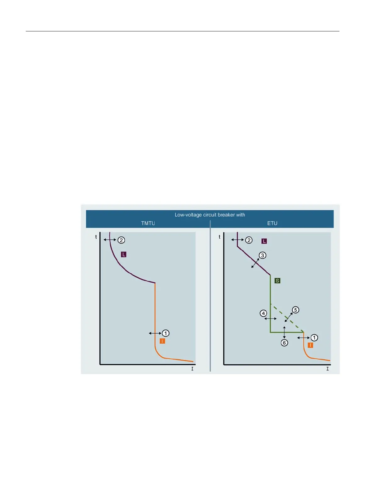
Tripping characteristics up to a tripping time of ≥ 1 ms are represented graphically. In order
to ease the coordination of different protection devices, the current is specified as a multiple
of the current setting value and the time is specified in seconds.
Tripping characteristics for thermal-magnetic trip units
Characteristics are displayed graphically in the double-log coordinate system (cf.
IEC 60947-2, paragraph 4.7.4 and IEC 60269-1). The ratio of current to time is 2: 1.
Tripping characteristics for electronic trip units
Characteristics are displayed graphically in the double-log coordinate system (cf.
IEC 60269-1). The ratio of current to time is 1: 1.
Response threshold of the long-time delayed
protection, thermal
Delay of the short-time delayed protection
Response threshold of the long-time delayed
protection
Response threshold of the instantaneous
protection
Delay of the long-time delayed protection L Overload range
Response threshold of the short-time delayed
protection
S Short-time delayed short-circuit current
range
I
2
t characteristic ON/OFF of the short-time
delayed protection
I Instantaneous short-circuit current range
 Loading...