EasyManuals Logo
Home>Siemens>Control Unit>SIMATIC CPU 410

Siemens SIMATIC CPU 410 User Manual

Siemens SIMATIC CPU 410
434 pages
To Next Page IconTo Next Page
To Previous Page IconTo Previous Page
Page #411 background imageLoading...
Page #411 background image
Connection examples for redundant I/Os
C.21 SM 322; DO 4 x DC 24 V/10 mA [EEx ib], 6ES7 322–5SD00–0AB0
CPU 410 Process Automation/CPU 410 SMART
System Manual, 05/2017, A5E31622160-AC
411
C.21
SM 322; DO 4 x DC 24 V/10 mA [EEx ib], 6ES7 322–5SD00–0AB0
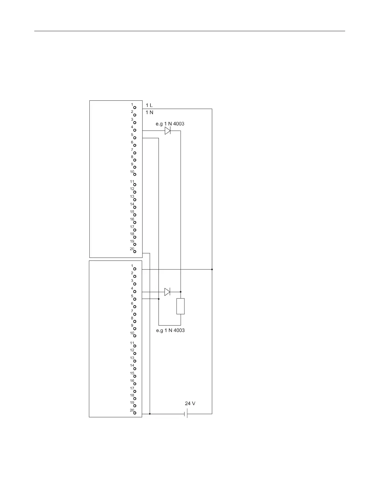
The diagram below shows the connection of an actuator to two SM 322; DO 16 x DC 24
V/10 mA [EEx ib]. The actuator is connected to channel 0. Suitable diodes are, for example,
those of the series 1N4003 ... 1N4007, or any other diode with U
_r
>=200 V and I_
F
>= 1 A
Figure C-19 Example of an interconnection with SM 322; DO 16 x DC 24 V/10 mA [EEx ib]

Table of Contents

Questions and Answers:

Question and Answer IconNeed help?

Do you have a question about the Siemens SIMATIC CPU 410 and is the answer not in the manual?

Siemens SIMATIC CPU 410 Specifications

General IconGeneral
BrandSiemens
ModelSIMATIC CPU 410
CategoryControl Unit
LanguageEnglish

Related product manuals